|
Building the Tom
Henry RS
Part Six: Service, Seating, Tuning, an SS Hood and
Nitrous Oxide End the Project
by Hib Halverson
|
 |
|
Image: CHpg Staff. |
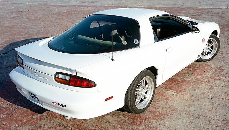
We begin this final
part of the Tom Henry RS project with how we solved a
brake problem and how we found out later it was
self-inflicted. For most of this project, the Camaro's
brakes have been stock calipers with upgraded brake
rotors from Baer Brake Systems.
 |
|
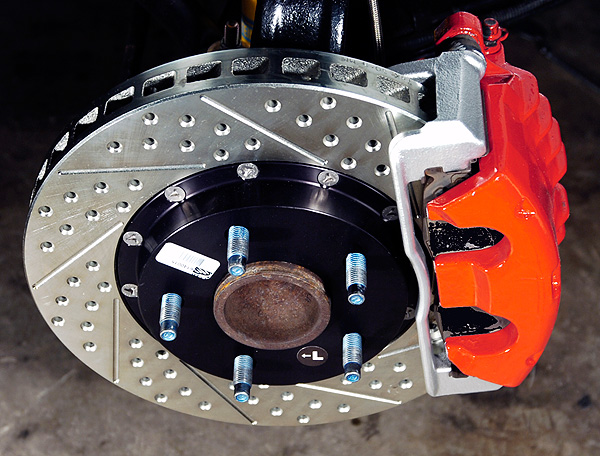
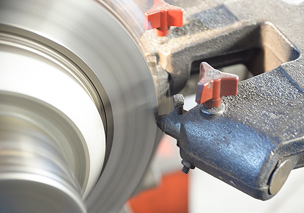
The THRS
front brakes uses drilled and slotted Baer two-piece
rotors and stock calipers. Image: CHpg Staff.
|
|
In the run up to this
part of the THRS series, we started feeling brake
shudder during braking from highway speeds and the
problem became progressively worse. Thinking this was a
thickness variation or runout problem, we measured both.
Turns out, we were wrong. Our Baer rotors were within
factory limits for thickness variation and runout.
Further road testing
demonstrated that, at slow speeds, just before the car
came to a stop, the shudder's frequency became low
enough that we could feel a back-and-forth sort of
"rocking motion". We pulled the rotors and inspected
them carefully. We saw sections of gray mixed with
sections of normal surface appearance. Deciding this was
a problem with transfer of brake pad material to
sections of the rotor and thinking we could remove it
with abrasives, we abraded them using an air grinder
fitted with coarse, non-woven, metal finishing discs
from Standard Abrasives. That didn't have much of an
effect and the brakes still shuddered.
We had several
conversations with Rick Pojman, the Customer Service rep
at Baer Brake Systems. He said that uneven transfer of
pad material to the rotor surface can be caused either
by brake pads which were not properly bedded or by pads
which have been overheated. If the problem was
overheating, we had made the wrong choice in pads and a
more aggressive pad might be necessary.
 |
|
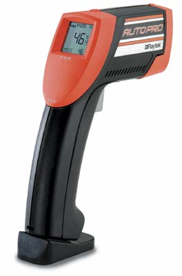
A benchmark of the
service trade for IR thermometers is this Raytek
ST-25. The one in our toolbox is ten years old and has
been indispensable when we need to measure temperatures
of various parts on a car. Image: Raytek Corporation. |
|
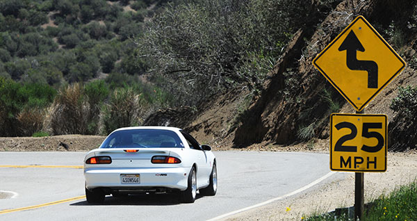
We needed to take
some brake temperature information before we could
decide whether or not we were going to change to a
different brake pad. We drove up into some nearby
mountains then came back down the same curvy road.
Several different times we stopped in a safe spot and
shot one of the front rotors with our Raytek ST-2 Autopro infrared thermometer. The highest temperature we
recorded was 519°F. Given that we never exceeded 80-mph
and, because most of the braking areas were at the end
of straights, the brakes were cooling between
applications; we figured our peak brake temp was higher.
We also noted that the brake shudder problem had become
much worse. After our brake temp testing session, back
at the shop, we pulled all the brake rotors again.
Looking at the
fronts, it was obvious that the problem with pad
material transferring to the rotors was more serious
than before. That along with our temperature readings
had us believing our problem was that we were exceeding
the design envelope of the brake pads.
|
We contacted Baer's
customer service agin, this time asking advice on what
to do with our rotors. The always-helpful, Rick Pojamn
said that a temporarily switch to a racing pad will wipe
the transfer away. He added that the only surefire ways
to fix the problem are either to machine the rotors or
replace them.
Machining works well
provided the rotors has minimal wear, the brake lathe
operator knows how to apply the proper final finish and
the amount of machining required is .005-in. or less. If
the rotors are close to or below minimum thickness,
rotor replacement is your only choice.
|
 |
|
Since the Baer rotors
had only minimal decrease in thickness, we decided to
fix the pad transfer problem by having the rotors
machined just enough to remove the coating of pad
material. Image: CHpg Staff.
|
Our solution was
two-fold. First, we took the rotors to Bob Woolever's
Tire Shoppe and had Bob machine the rotors just enough
to remove the pad material. This amounted to about a
.005-in. thickness reduction and left us well over their
minimum thickness specifications.
Next, we dialed up
Porterfield Enterprises, a specialist in
high-performance street and racing brake pads. The
company was started in the mid-'80s by the late Andy
Porterfield, a semi-professional road racer who spent
most of his career driving Camaros and Corvettes in the
SCCA Trans-Am, GT-1 and various "outlaw" road racing
series on the West Coast. In 1986 he became the U.S.
distributor for Ferrodo racing brake pads and, in the
near 30 years since then, Porterfield Enterprises has
become the go-to source for racing brake pads in the
U.S. Porterfield is the only vendor which sells
Raybestos racing brake pads to consumers.
|
 |
|
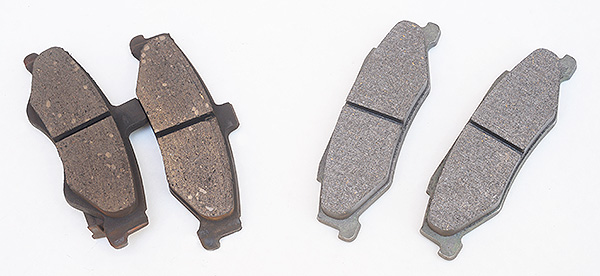
The difference
between street pads (left) and racing pads can be seen
in the texture of the pad material. Also, the Raybestos pads (right) for the rear are only
available in a C5 Corvette pad which fits the '98-'02
Camaro rear caliper but requires the pad abutment shims
be deleted. That can cause some occasional rattling.
Image: CHpg Staff.
|
After talking with
Porterfield's, Tim Gray, we decided to try a set of pads
made with Raybestos ST-43 compound. Raybestos terms this
a full race pad compound but it can be used on a road
car if one is willing to accept a bit higher pedal
effort when the brakes are cold, some brake noise and
quite a bit more brake dust than is emitted by stock
pads or even some "performance street" pads.
Additionally, these pads are harder on rotors. If you
don't like brakes squeaking and dusting or you want
rotor life the same as stock; don't use this brake pad,
however, if you want brakes that really work well and
are willing to replace rotors more often, the ST-43 is
the way to go.
There are also a
couple of "alternative fit" issues with these pads.
First, they don't have the stock GM wear indicators
which "screech" when the pads are near gone so use of
them requires occasional brake pad checks. Secondly, the
rear pads, while they fit Camaro rear calipers, are
actually a C5 Corvette pad. Corvette rear pads have
three locating tabs on their backing plates. If you
install the calipers and caliper mounting brackets as a
unit, there is no installation issues, however, if you
change pads by simply removing the caliper from the
caliper mounting bracket, you have to put the pads into
the grooves in the mounting bracket then carefully work
the caliper over the locating tabs. Doing that is a bit
awkward but patience and care will get you through the
process.
|
 |
|
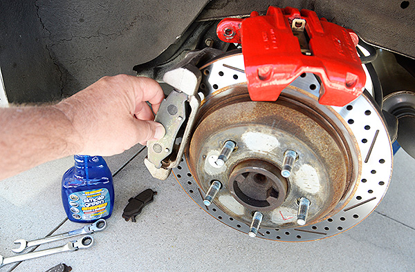
We cleaned up the
parts with a little Simple Green Motorsports Degreaser
then installed the Raybestos pads. Image: CHpg
Staff.
|
So far the ST-43s are
working well with no signs of brake shudder and–holy
crap–do they stop! When we hit the brakes, the
Porterfield/Raybestos pads really bite hard, stop quick
and don't fade.
|
 |
|
Braking
performance was markedly improved. We've run the Raybestos pads we got from Porterfield Brakes for
several months and, so far, no signs of brake shudder.
|
Oil Change and Oil
Leaks
Because we're going
to put the car back on the chassis dyno later in this
article, and it's been quite a while since we changed
the oil in the THRS's engine, we got the car up in the
air, drained the crankcase then pulled the filter off.
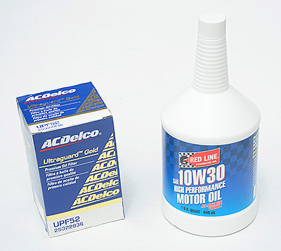
In went five quarts of fresh Red Line 10W30 Engine Oil.
Next, we prefilled a new ACDelco UPF52 Ultragard Gold
oil filter and screwed it in place. If you've followed
this project from the start, you know we've used nothing
but Red Line 10W30 in our mod'ed three-eight.
|
 |
|
ACDelco's
Ultragard Gold is GM's premium aftermarket oil filter.
We use the UPF52 which not only is an upgrade over
regular ACD "Duragard" design but also is a longer
filter than the PF47 which is stock on a 3.8. Normally,
'52s are used on trucks. We've been using Red Line 10W30
engine oil in the Tom Henry RS engine since the car was
new. Image: CHpg Staff. |
There are two main
reasons for that. First, we prefer Red Line's robust
base stock combination of esters and polyalphaolefins
(PAO) and the better performance and protection at high
oil temperatures they provide. The Tom Henry RS doesn't
have an engine oil cooler and we're making 50% more
power than stock which means, when we're running the
engine hard for sustained periods–say we take a sporting
run over one of our favorite twisty roads–we see as much
as 260°F oil temperature. We use an AutoMeter Sport-Comp
II electric temperature gauge (PN 3656) and its sensor
is in the oil filter housing, perhaps the coolest place
in the oiling system. If we have 260° at the oil filter,
the oil may be 280° in bearings. Under that kind of
abuse, the margin of safety offered by Red Line's
thermal stability is desirable.
Second, we can run
Red Line 10W30 to extended drain intervals as a way of
recovering some of the oil's higher cost . Since the
1000 mile mark, the V6 in our Camaro has used Red Line
and oil changes have been done every 18,000-20,000 miles
with a filter change every 4000-5000 miles. We have over
a dozen years of spectrographic oil analysis data to
back up our advocacy of Red Line and extended drain
intervals.
The car's Tremec T-5
five-speed manual transmission has been in service just
under 120,000 miles and lately, we noted it has been
weeping lubricant out of its rear seal. When we grabbed
the driveshaft and pushed it up and pulled down, we
could see the lip of the rear seal was deforming too
much, indicating that the extension housing bushing was
probably worn out. Considering how hard we've beat on
the trans in this car, even Red Line MTL's superior
lubrication couldn't make that bushing last more than
120K.
Tom Henry Racing's
Parts Manager, Stan Lorence, told us GM does not service
the bushing. You have to buy the whole housing to get
it. The cost? Take a deep breath–630 bucks. We about had
kittens when we heard the number.
We started looking on
the aftermarket for the bushing. A session with Bing
found one at
Manualtransmissionparts.com
in Alabama so we ordered the bushing (PN 44066) along
with a rear seal from Tom Henry Racing.
|
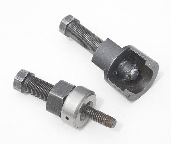
 |
|
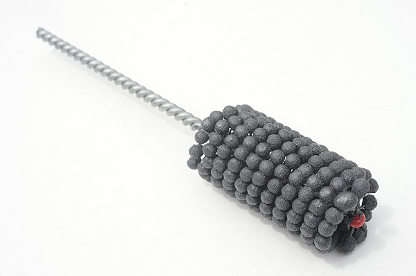
We didn't expect the extension housing
bushing we bought to be "hone-to-fit"
but it was. Initially, we could not
install the driveshaft into the
transmission, so we had to get the
housing off a second time and hone the
bushing with a Brush Research
"Flex-Hone". Image: CHpg Staff. |
With the car up on
stands, we removed the gearbox, unbolted its extension
housing then, took it to a nearby automotive machine
shop which had a hydraulic press and had them change the
bushing. Back at our shop, we honed the bushing's inside
diameter with a 1.375-in. 240-grit Flex-Hone (PN
BC13824) to fit the output yoke on our Inland Empire
Driveline Service aluminum drive shaft, wiped some Red
Line Assembly lube in the I.D. of the bushing and
reassembled the trans.
Since we had the
trans out and its clutch release bearing assembly was
ten years old, we replaced it with a new unit (PN
24264182) from Tom Henry Racing. We put the trans back
in, reinstalled all the brackets and mounts. We wiped
some more Red Line Assembly Lube on the O.D. of the
yoke, then reinstalled our EDS aluminum shaft.
|
 |
|
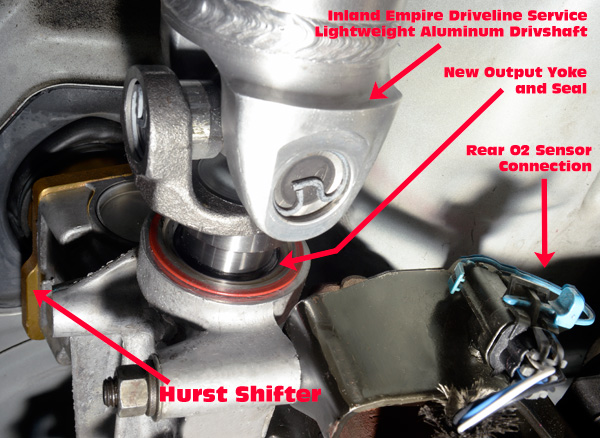
Worm's eye view of
the back of the transmission. When the
extension housing bushing is worn, the
driveshaft front yoke can "wobble" on
the output shaft splines. Once the end of
the yoke moves a distance greater than the seal's lip
can expand, it starts to leak. Image: CHpg Staff. |
We filled our T-5
with "MTL" which stands for "manual transmission
lubricant", Red Line Oil's low-viscosity, GL-4 gear
lubricant. MTL is a performance upgrade over the ATF
which most people use in T-5s and a better choice for
severe duty, such as transmissions behind modified
engines in street high-performance or racing
applications. It's GL-4 rating means it's formulated
specifically for lubricating spur gear or helical gear
transmissions. It's, also, blended to have just the
right friction coefficient for optimal performance of
cone-type synchronizers. While it's rated 75W80 on the
gear lubricant viscosity scale and 5W30 on the engine
oil scale, both of which are somewhat higher viscosity
than ATF; MTL still is a low-vis trans lube like GM's
"Synchromesh" or "Manual Transaxle" lubricants. Red Line
MTL has good low-temperature shift feel,
high-temperature stability and overall lower shift
effort.
|
 |
|
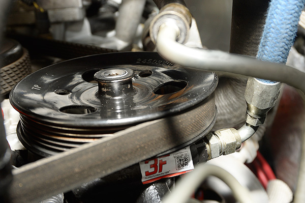
Worm’s eye view of the power steering pump. It looks
hard to change but, as long as you have pulley removal
and installation tools, changing it is pretty easy. The
key task in the pump change is vacuum bleeding the
system once the pump is installed. Image: CHpg Staff
|
The five-speed
was not the only thing leaking. During our work under
the car to R&R the transmission, we noted the power
steering pump was weeping fluid, too. Like the cost of
the tail housing, the cost of a new steering pump was
over-the-top, so we ordered an A-1 Cardone
remanufactured pump from Rockauto.com (PN 20905). We
like Cardone’s reman parts and, when we get them from
Rockauto.com the price is competitive and the service is
quick.
The pump replacement
was straight forward. We used a Bosch Automotive power
steering pump pulley removal tool (PN J-25034-C) to get
the pulley off, disconnected the hoses then unbolted the
pump. Putting the
Rockauto.com
reman in place was, the reverse of removal. With the new
pump in place, we used another tool (PN J-25033-C) to
reinstall the pulley. Finally, we filled the pump
reservoir with Red Line Synthetic Power Steering Fluid.
Again, we choose Red Line because it's a better for high
performance use than the ordinary petroleum-based
fluids. We bled the air out of the steering system per
the Service Manual's instructions using a tool we made
from a bathtub stopper.
|
 |
|
Our Bosch
Automotive power steering tools. At
right is the pulley removal tool. At
left is the installer. Image: CHpg Staff. |
Lastly, we had a
leaking rear axle shaft seal on the right side so, we
dropped the rear axle cover, removed the axles and
replaced the axle seals on both sides with parts we
ordered from the Tom Henry Racing parts department.
|
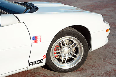 |
|
The Fikse
Profil 5 in 17x9-inch size. These wheels have been on
the car for eight years. They look almost as good now as
they did when they were installed in 2006. Image: CHpg
Staff.
|
Round and Black
Several years ago, we
put Fikse Profil 5S wheels on the Tom Henry RS. Because,
Fikses are so light for a street wheel, we were able to
go from a 16x8 to a 17x9.5 yet not increase unsprung
weight. We expected this, considering their racing
pedigree. Cars on Fikses have won both the World's
preeminent endurance races, the 24 Hours of Daytona (4
times!) and the 24 Hours of LeMans.
The Fikse Profil 5S
is a modular design with a rotary-forged, CNC-machined,
clear powder-coated, aluminum center. The rims are
forged, heat-treated aluminum. "TechniPolish" is Fikse‘s
standard finish and features a robust, liquid-cured,
clearcoat on the diamond-turned center section. The
mirror-polished rims are left uncoated to allow for
touch-ups as needed in case of minor scrapes.
|
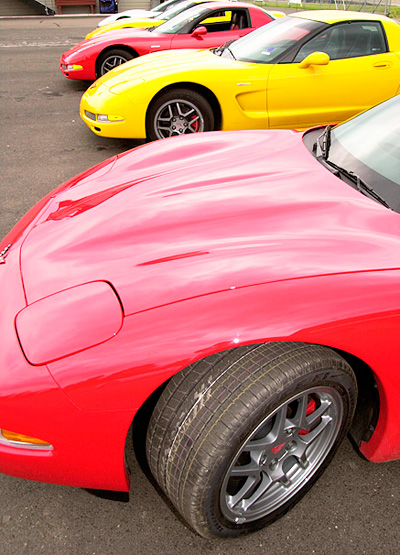 |
|
Shown here during the
tire's press introduction in the summer of 2000, the
Goodyear F1 Supercar was designed for the C5 Corvette
Z06.
Image: CHpg Staff.
|
The wheel change
allowed us a significant tire improvement: the
265/40ZR17 Goodyear F1 Supercar. The Supercar was
engineered specifically for the C5 Corvette Z06 of the
early-'00s, but Goodyear's design has held up well and
is still a good choice in ultra-performance summer tires
of that size. It is one of a few tires which bridges the
gap between all-round, performance tires, such as the
Goodyear F1 GS-D3, which we used when we had 16s on the
car, and DOT-approved, radial road race tires which are
not acceptable for general street use because of short
tread life and almost nonexistent, wet traction. While
the F1 Supercar is more sticky than some other tires
that size, it's not the drag race tire that a "drag
radial" from Goodrich, Nitto or Goodyear might be.
Nevertheless, the Supercar makes a great "compromise"
tire which performs well in a variety of street
performance situations other than heavy rain or freezing
weather.
|
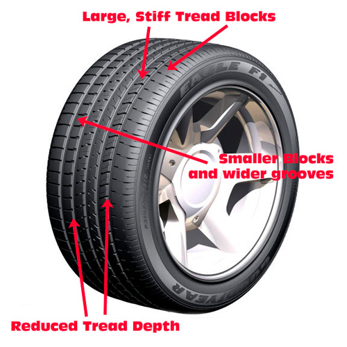 |
|
The outside
of the F1 SC has large, stiff tread blocks and reduce
tread depth. The stiffer the tread and the more shallow
the grooves, the less the tire's contact patch "squirms"
and the better the tire handles. The smaller blocks and
wider grooves in the inside of the tread give the
Supercar acceptable performance if we get caught on a
wet road. Image: Goodyear Tire and Rubber Co.
|
|
 |
|
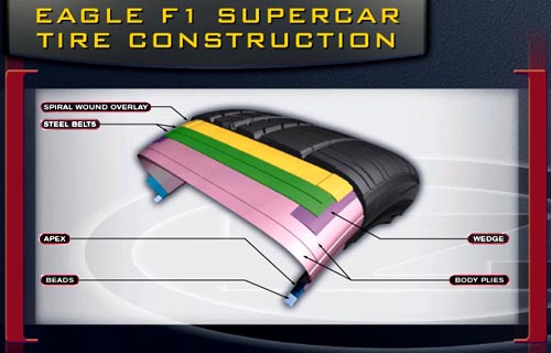
This drawing
illustrates what's under the tread of a
F1 Supercar. The wedge, spiral-wound
overlay and the steel belts contribute
to the tire's performance. Image:
Goodyear Tire and Rubber Co. |
The main advantages
to the Tom Henry RS with the F1 Supercars are improved
at-limit handling due to more traction coming from a
wider tread, more aggressive rubber compound, slightly
reduced tread depth and a tread block design skewed
towards handling. Additionally, the F1 Supercar casing
design improves steering feel and yaw response.
One characteristic of
the F1 Supercar has surprised us and that's tread life.
We ran them on the car for seven years, putting them on
in the early Spring, Summer and Fall and taking them off
during the Winter. When that first set of Supercars was
down to the wear indicating bars, there was no question
as to our replacement choice. We had Tom Henry Racing's
Stan Lorence order another set of Goodyear F1 Supercars.
|
 |
|
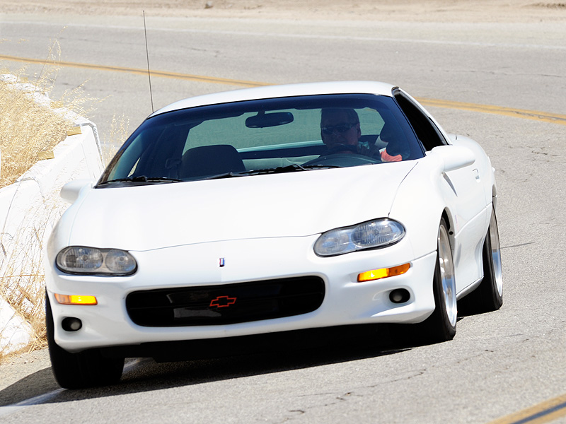
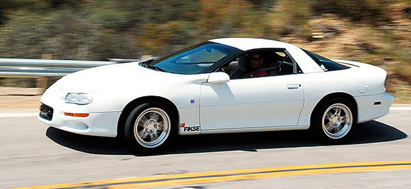
Though the F1
Supercar's design is a bit dated, in the 17-inch size we
use on the Tom Henry RS, it provides very good lateral
grip as shown there in testing during the suspension
work we did for Part 5. Image: CHpg Staff.
|
Inside Improvements
Now, for some
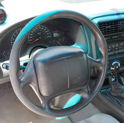
interior upgrades. First thing was to fix the car's
nasty-looking steering wheel. Most V6 Camaros have the
base wheel, a simple, rubber-covered unit. On the upper
(where you put your hands) and lower (where your knees
slide under it) parts of the wheel, the smooth black
surface of the rubber had worn away exposing a
ugly-looking and rough-feeling, dark gray, sponge-like
material.
We contacted two
companies which advertise late model steering wheel
repair and restoration: Mike's Custom Steering in
Kentucky and Dallas Custom Steering Wheel in Texas. Both
were unwilling to refurbish the THRS's stock steering
wheel at any price.
|
 |
|
After 13
years of use, the car's steering wheel–mainly the top
1/3–had worn severely.
Image: CHpg Staff.
|
Our next idea was to
look for a new or used steering wheel. As for new–no
way. Tom Henry Racing's Parts Manager, Stan Lorence,
told us they're long since discontinued and no dealer in
the country has any "new old stock". As for used
units?Turns out, wheels for fourth-gen base cars in good
condition are difficult to find. We saw several on eBay,
but all were wearing the same way as ours.
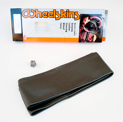
We decided to install
a leather rim cover, manufactured by Wheelskins, on the
existing ugly wheel. Wheelskins are made of top-quality
cowhide produced in the U.S. and can be had in a number
of colors. The lacing is made from a nylon material
similar to that used in "parachute cord" and is waxed to
make the lacing process easier.
|
 |
|
Our solution was a Wheelskin kit. It comes with everything needed to
recover the wheel.
Image: CHpg Staff.
|
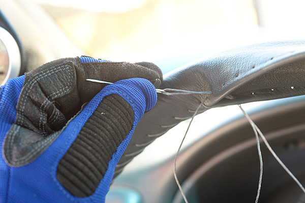
A Wheelskin is
installed by stretching it around the rim of the wheel
then taking the lacing tool–a large, dull-tipped needle
included with the product–and the nylon cord and lacing
the cover's sides together. The holes for the cord are
already punched in the leather.
|
 |
|
While the big
needle used to thread the Wheelskin's lacing is not
really sharp, it's easier on the fingers if you have a
mechanic's glove on the hand that holds the needle.
Image: CHpg Staff. |
Installing the
Wheelskin is easy work but tedious. The instructions
suggest installation takes an hour but, for someone
who's never done a Wheekskin before–that's us–it's more
like three hours, working slowly and following the
instructions to the letter.
|
 |
|
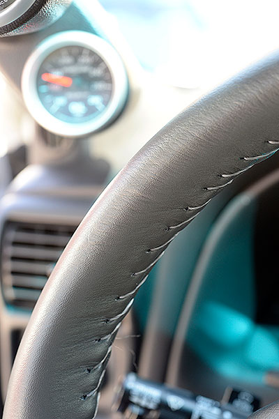
Once the Wheelskin was in place, the THRS Camaro's steering wheel
looked and felt much better. Image: CHpg Staff.
|
When we were done,
the steering wheel in the THRS looked great and felt
much better in our hands than did the original rubber
covering, even when it was new. Another feature of the
Wheelskin treatment we liked is that it increased the
diameter of the wheel rim by about a 1/16 of an inch
which doesn't seem like much but it contributed to the
steering wheel feeling more substantial. Two thumbs up
for the Wheelskin because, literally–as when one's hands
are positioned correctly on the wheel, both thumbs point
up–and figuratively as we really like this product.
The next step was to
do something about the car's seats. The stock seats'
lack of side support was our main problem. We tried two
solutions. The first, our "quick-and-cheap" solution was
to remove the driver seat and have a local upholstery
shop increase the amount of padding on the edges of the
back and the cushion and recover the seat. It had the
effect of letting the driver settle deeper into the
cushion and back, thus increasing side support.
Considering the low cost, this was a great modification.
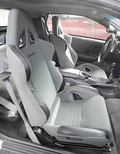
"Stage Two" of our
seating program was to replace the stock seats with a
pair of Scat Enterprises Procar "Rave" seats (PN
80-1600-64L and 80-1600-64R). which are an affordable,
"weekend warrior" grade of racing seat with the added
convenience of a reclining back.
|
 |
|
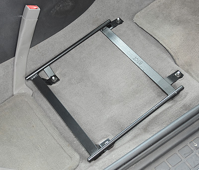
The Procar
seat installation begins with the adapter bolting to the
stock seat mounting holes. Image: CHpg Staff. |
Procar Raves are
installed using a set of Scat's adapter brackets (PN
811068, left, and PN 811069, right) which are specific
to the 4th gen cars. You're supposed to remove the stock
seats, bolt the brackets to the stock seat mounting
holes then install the seats onto the brackets.
|
 |
|
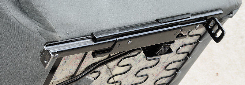
This shows the one
problem we had with the installation:
the mounting system needing to be
modified because of clearance problems.
The mod was cutting the lower two holes
of the front of each seat track.
Image: CHpg Staff. |
Unfortunately, it
wasn't that easy. In theory, Procar's method of fitting
a single seat design to a wide variety of cars is pretty
slick. In practice, it didn't work well on our Camaro.
The mounting tabs on the seats have three holes,
intended to give the installer a choice of height or
rake depending on which holes are used to bolt the seat
to the adapter bracket. During our test fit, we couldn't
get the seat low enough because the front mounting tabs
bottomed on the floor of the car before their uppermost
holes, which provide the lowest mounting height,
lined-up with the holes in the bracket. The seat was
tilted back too far and the front was too high. The
solution? A cutting wheel on our air grinder with which
we removed most of the front mounting tabs. Once we did
that, the Rave bolted in and the seat rake was better.
|
 |
|
These
seats were priced right, looked great
and had the side support typical of a
racing seat, but in our tests, they
didn't work well for people with small
butts and short legs. Image: CHpg Staff. |
We road tested the
Raves for several weeks. The increase in lateral support
over our modified stock seats was significant. Lumbar
support was better, too. A downside was the cavity in
the seat cushion was too long for someone with shorter
legs. With my butt against the seat back, I had to move
the seat forward to reach the pedals. If I sat with
front of the seat supporting my calves, there was a big
gap between my butt and the seat back. Folks with longer
legs probably would enjoy the Raves more that we did.
In other interior news, right in the middle of getting
this article together, the driver side window on the Tom
Henry RS quit working. After diagnosing the problem,
it's obvious to us that, If your Camaro is high
mileage–like the Tom Henry RS is at 120,000 miles–it's
not "if" but "when" the side window mechanism will fail.
This is because there is
a durability problem with the window sash channel which
to which the side glass is attached. At either end of
this channel are brackets to which the glass is attached
with blind or "pop" rivets. The rear bracket also holds
the axle for the roller which runs in the vertical
window lift channel. When the widow is moving down and
this roller gets to the bottom of the vertical channel
it hits a stop. The force of the roller pushing
against the stop causes the axle to be forced sideways
and that causes the sash channel rear bracket to flex.
Over a period of time, that flexing eventually cracks
the bracket and the crack grows until either the axle
falls out or the section of the rear bracket holding the
axle breaks off. Once that happens the window lift
fails.
The pop rivets holding
the glass to the sash channel are not the typical
aluminum type with which most DIYs are familiar. They
are made of steel and require a long-handled, commercial
grade rivet "gun". In fact, at the assembly plant, the
window glass was riveted to the channel brackets with
an industrial-type, power-operated rivet gun. Most DIYs
are not going to have access to a factory-type rivet gun
and even the manually-operated, long-handled commercial
guns are not going to be a tool to which most DIYs have
access.
I ran into this riveting
problem with the THRS when the driver side window
mechanism quit working. I disassembled the door, noted
that the rear sash channel bracket had broken. I found
the axle at the bottom of the door. To repair or replace
the sash channel, you have to remove the glass, first
and to do that, you must drill out the rivets. Once you
do that, you can replace the sash channel. Once the new
sash channel in in place, the Factory Service Manual
says to replace the rivets with new units from GM.
Problem was, no way did I own a pop rivet gun which
could install steel rivets.
|
 |
|
This glass sash
channel stud was used on all 2nd gen
cars. GM could have kept using it on the
3rd and 4th gen cars, but, in the
interest of quicker assembly, switched
to rivets. Obviously, they decided not
to allow easy service which is kinda
stupid considering side glass
replacement is not an unusual need.
Image: Year One, Inc. |
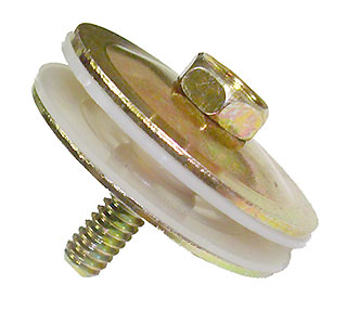
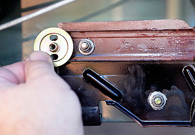
My solution? Oldskool.
The '67-'81 Camaros and Firebirds used bolts and large
"washer/nuts" rather than rivets to hold the glass to
the sash channel. It was very simple to order three door
glass sash mount stud assemblies (PN598) from Year One,
discard the large washer nuts and replace them
with smaller, conventional 1/4-in. flat washers and
1/4-in. self-locking nuts then use that set-up to
attach the glass to the sash. That was much easier
than trying to find a tool to install new blind rivets.
|
 |
|
This is
how the installation looks once the stud
is in place. You have to supply your own
1/4-in. flat washer and self-locking nut
both of which are easily to find at any
hardware store. For comparison, the
washer/nut which comes with the stud is
shown. That part you discard. Image:
Author. |
Once I had the parts order from Year One, I had my
driver side door back together in about an hour. The
window mechanism works great. The sash mount studs can
be found at
https://www.yearone.com/Product/1967-81-camaro/sm598
Getting with the
Program
|
 |
|
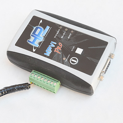
The VCM Suite
configuration we picked was the GM base and the uplevel
MVPI Pro. Among other features, the MPVI Pro differs
from the base model in that it has the hardware you need
to bring a wide-band oxygen sensor signal into VCM
Scanner so you can have wideband data. Image: HPTuners
|
Reprogramming the
calibration of our V6's ECM was required because of the
extent of its modifications–Comp cam, Mark DeGroff
ported/polished/cc'ed heads with bigger valves, Katech
valve springs and titanium retainers, Yella Terra 1.8:1
rockers, Extrude Honed intake manifold, Whisper Lid,
headers, MSD coils, Denso IT-20 plugs and a Flowmaster
exhaust.
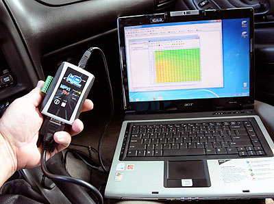
We started reworking
the THRS calibration in Part 5 and we finished it for
this final installment of the series. We work with
HPTuners' “VCM Suite” software, which we ordered from
Summit Racing Equipment because the price was
competitive and Summit turns around orders quickly. VCM
Suite includes “VCM Editor,” an application for
calibrating 1997 or later GM vehicles, and "VCM
Scanner", a data logging app. We like HPTuners because
it supports a wide range of GM engine controls platforms
and it's popular tuning software amongst DIYs and
professional calibrators, alike. HPTuners runs on PCs
using Windows XP, 7 or 8. At Tom Henry Racing, we run it
on an old Acer 5670 laptop loaded with Win 7.
In Part 5, we didn't
have a wideband oxygen sensor on the car, yet, so we
confined our tuning to some part throttle work which can
be done with the OE narrow band sensors. We began our
cal work for this article with a look at what the engine
was doing at wide-open throttle. The car has never felt
quite right at high-rpm. Not that it ran poorly–it just
didn't feel right, especially, when running above 5700
rpm on a cool day at sea level.
|
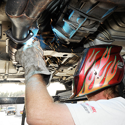 |
|
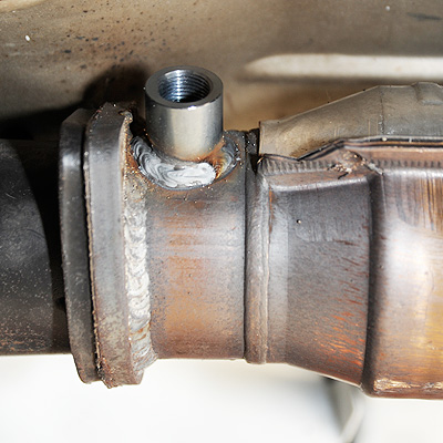
To install an
O2S bung, the exhaust is drilled just downstream of the
2-into-1 collector and just ahead of the catalytic
converter. The hole is deburred, then the sensor bung is
welded in place. Image: CHpg Staff.
|
|
 |
|
Packaging
constraints dictated that we have the sensor bung
pointing to the center of the car. Image: CHpg Staff. |
A wide-band oxygen
sensor is required for calibrating wide-open throttle,
so the first thing to do was install one. We took the
car to Big John's Performance Center and had their ace
fabricator, Steve Munson, install an MSD oxygen sensor
bung in the exhaust just ahead of the catalytic
convertor. Then, we ordered Bosch Aftermarket (PN 17014)
and Denso (PN-234-5117) wide-band sensors from
RockAuto.com.
|
 |
|
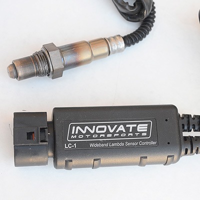
Initially, we
tried the recommended Bosch sensor with the LC-1. Image:
CHpg Staff.
|
We also ordered an
Innovate Motorsports LC-1 controller (PN 3744) from
Summit. Innovate markets a variety of wideband systems
and was suggested to us by the Tuning School which is
discussed in our sidebar about learning calibration.
|
 |
|
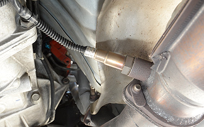
We installed the
Bosch wideband sensor then looped the cable up and over
the exhaust. Image: CHpg Staff.
|
|
 |
|
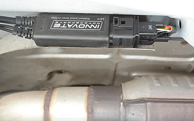
In a
perfectly-sized spot between the floor
and the exhaust shield, we mounted the
LC-1. Since this was a temporary
installation, after we shot this image,
we clamped the unit in place.
Image: CHpg Staff. |
We connected the
LC-1, HPTuners' "MVPI" (short for "multi-vehicle
protocol interface") which comes with the VCM Suite, an
LED indicator, a push-button and a wiring harness we
fabricated according to Innovate's and HPTuners'
instructions. All that links to our laptop with a USB
cable. While Innovate Motorsports supplies its own data
logging software, so we could log wideband and engine
controls data together; since we chose the uplevel "MVPI
Pro" which as the capability of logging data from up to
four 0-5-volt, external sources, we could configure VCM
Scanner, to record the LC-1.
|
 |
|
HPTuner's
standard MVPI, the Pro model looks the same except for
the MPVP Pro has a, green, push-in connector on the
side. Provided they have analog outputs of from 0 to
5-volts, up to four external devices which you wish to
log can be wired to that connector. Image: CHpg Staff.
|
We screwed a Bosch
sensor into the Camaro's exhaust, set up HPTuners VCM
Scanner to display the wideband data then headed for
Westech Performance Group and its Superflow chassis
dyno.
We made three runs.
Afterwards, studying wideband data from VCM Scanner, I
could see we still had problems with power enrichment
(PE). At the low end it was at 0.86-lambda, which is
about right, but then, it would get rich until around
5500 rpm after which, the mixture would begin to lean
out. It would get back to .86λ then continue going lean.
|
 |
|
With the
LC-1 connected to the MVPI Pro though the wiring harness
we fabricated, we can look at wideband data in synch
with other engine controls data using VCM Scanner.
Image: CHpg Staff. |
While we had done
some work to the "PE Fuel Adder RPM vs. Time" table for
Part 5, we were still having problems with rich mixture
once PE was enabled, so we just zeroed that table for
WOT periods shorter than 19-seconds then ran a few more
dyno passes. Starting at 4750 rpm, VCM Scanner showed
high injector duty cycles–understandable considering, at
the time, we were making around 270-hp with injectors
sized for 200. In fact, as we approached the rev
limiter, the system was commanding over 100% duty cycle,
which, of course, is impossible to achieve, because, at
100%, the injectors are held open.
|
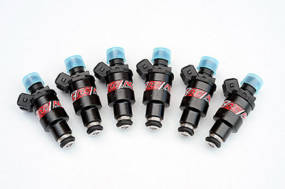 |
|
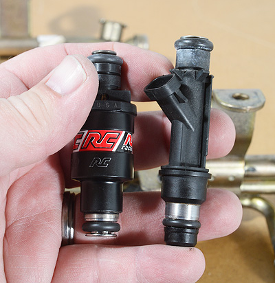
Our choice was a set of RC Engineering
SL2-0240, 240-cc/min. injectors. Image:
CHpg Staff. |
We asked RC
Engineering, a leading supplier of aftermarket injectors
for help. RC's John Park told us not only did we likely
need injectors capable of flowing more fuel but that
fuel mixture can get erratic above 80-85% duty cycle for
extended periods because injectors overheat and may
become difficult to control. RC Engineering recommended
upgrading to a 240-cc/min. injector (PN SL2-0240) which
is a noticeable jump in fuel flow over the stock
206-cc/min, Delphi injector. RC injectors use the disc
fuel metering system, have corrosion-free, stainless
steel internal parts and are known for their tight
tolerance of flow spread (±1.5% or less) over a set of
six injectors. All sets of RC injectors are tested
before shipping and ours our went out the door with an
even better, 0.3% spread.
|
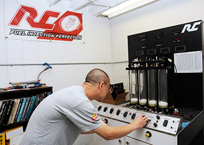 |
|
Every set of injectors is tested by RC
Engineering's John Park. Injectors, in
groups of up to four at a time are
tested for flow and spray pattern.
Image: CHpg Staff. |
What are the chief
advantages of RC injectors over the more common and,
admittedly, less expensive Bosch pintle injectors?
First, the disc injectors are less prone to fouling. The
pintle is a long shaft with a needle-like tip which
sticks through a hole in the bottom of the injector.
When the injector is energized, this pintle lifts and
fuel flows between its tip and the edges of the hole.
When the engine is
shut off, some intake valves are left open. Heat from
inside cylinders with open valves rise to the injector.
If there is fuel residue on the pintle tip protruding
from the end of the injector, the fuel residue begins to
bake onto the pintle. Also, carbon byproducts of
combustion can collect on pintle tip. Over time,
baked-on fuel residue and combustion byproducts may
build-up, causing poor spray pattern, lean mixtures,
drivability quirks and high emissions.
|
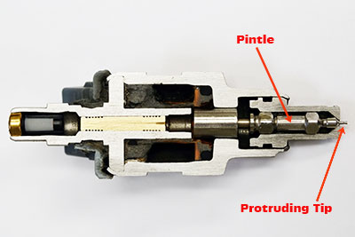 |
A cutaway Bosch-type, pintle injector.
Image: RC Engineering. |
|
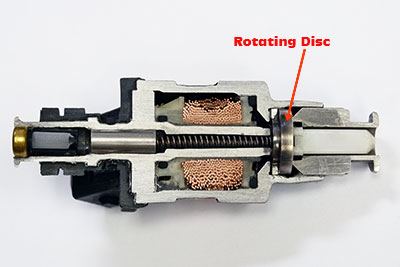 |
|
A cutaway of an RC Engineering, rotating
disc injector. Image: RC Engineering. |
When a disc injector
is energized, a tiny disc is raised off a seat and fuel
flows between the two. When the disc is off the seat it
may rotate. This type of injector is more resistant to
fouling because the disk and its seating surface are
recessed in the body of the injector and that has them
less exposed to heat.
The second advantage
comes from a difference in the mass of the injector's
moving parts. The disc's mass is about an eighth of that
of a pintle, thus disc injectors can respond more
accurately to short open times typical of idle and part
throttle operation. That gives disc injectors a wider
dynamic range.
|
 |
|
While the Delphi and RC injectors have
different overall lengths, the distance
between the injectors' O-rings is
similar and the RCs will fit with no
problems. Image: CHpg Staff. |
|
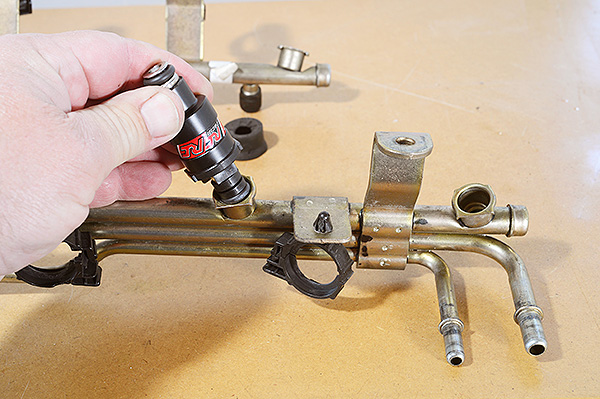 |
|
The RC injectors push into the same
mountings in the fuel rail as did the
stock Delphi units. Image: CHpg Staff. |
|
 |
|
Once you remove the alternator, getting
the fuel rail and injector assembly on
and off is easy. With its RCs in place,
we reinstalled the fuel rail. Image:
CHpg Staff. |
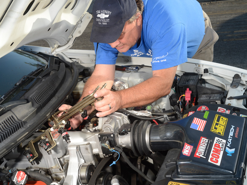
Installing
RCEngineering injectors is no more difficult than
replacing stock fuel injectors. Both types fit the stock
fuel rail and the injector mounts in the lower intake
manifold. Once you get the alternator and the ignition
system out of the way, use shop air or a shop vacuum to
remove any dirt and debris which might have accumulated
around the injector bases. Then, remove the fuel rail
and injectors. Remove the injector retaining clips, pull
out the old injectors. Then clean out the rail, install
the RCs, put the clips back on and reinstall the fuel
rail to the engine.
|
 |
|
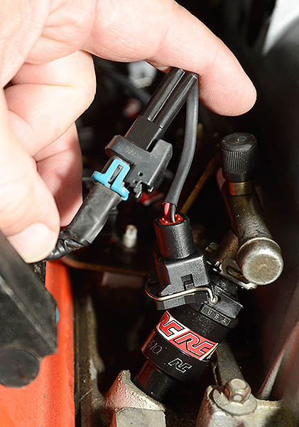
There is one feature which is quite
different on an RC injector and that's
its electrical connection. Initially, we
thought we'd have to splice and solder
the right connectors in to the THRS'
wiring harness which would preclude us
ever switching back, however, we
discovered that our fuel pump supplier,
Racetronix, sold "plug-and-play"
adapters which connected between the
stock wiring harness and the
RC injectors so we ordered a set of six
adapters. Image: CHpg Staff. |
The only feature of
these injectors that's different from stock are the
electrical connectors.The RC disc injectors use a
"minitimer" connector, whereas stock 3800 Series II
injectors use the "Multec II" connector. To make the
installation "plug-and-play," we ordered six Racetronix
adapter harnesses (IA-M2M) and connected them between
the OE injector connectors and the RC Engineering
injectors.
Calibrating for the
new injectors required a session on the RC Engineering
web site at
www.rceng.com
using its fuel flow and pressure calculator. We
converted our RC Injectors' 240-cc/min@43-psi flow
rating to what flow would be at the V6's observed,
50-psi fuel pressure–259-cc/min. Next, we converted that
into pounds-per-hour and using HPTuners VCM Editor,
entered 24.6-lb/hr. into the calibration as the flow
rate at zero manifold vacuum–wide open throttle.
A 3800 Series V6
calibration has injector flow numbers which vary
according to the effect manifold pressure has on the
injectors and on the fuel pressure regulator. To
populate this table with 100% accuracy, you'd have to
either flow test the injectors at a variety of MAP
levels and fuel pressures which, of course, is
impossible–unless you are GM Powertrain. We did the next
best thing: we figured the differences in flow on a
percentage basis for the stock injector flow data, then,
using those percentages, figured new data for the RC
injectors to put in the "Injector Flow Rate vs Kpa
vacuum" table. Finally, I programmed the pulse width
voltage offset data RC Engineering's John Park supplied.
This time, testing
showed that, at WOT, the air:fuel ratio was now more
consistent so, the next step was to reconfigure the
calibration's main VE table at high throttle openings to
better suit the changes in airflow caused by the
aftermarket camshaft profile, larger valve sizes, head
porting and intake manifold Extrude Honing.
|
 |
|
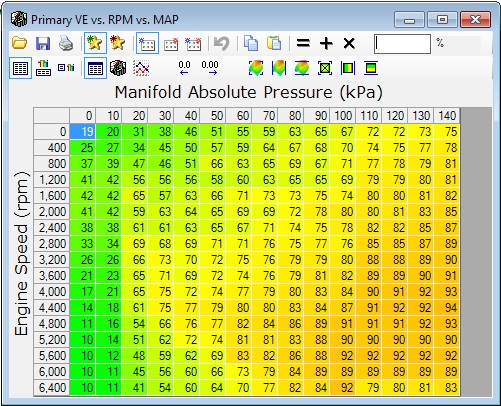
This is how HP Tuners displays the main
VE table. Changes can be made directly
in each cell. Any engine which has had
mods, such as a camshaft change, which
affect its volumetric efficiency, will
likely need tweaks to the main VE table.
Image: CHpg Staff. |
Some DIYs marginalize
the value of getting the main VE table right. Those who
do are either too lazy to do the work or don't
understand the need. If the VE table is stock, but your
engine has mods which affect volumetric efficiency, the
engine controls are going make incorrect assumptions as
to the amount of air entering the engine. Some rookie
calibrators use other methods to fool the engine
controls into delivering the right amount of fuel. This
may result in an inconsistent AFR when in PE and it does
not address the effect an inaccurate main VE table has
on part throttle drivability.
To get the VE table
right, be it on the dyno or on the test track, you have
to write a temporary calibration to the ECM which
disables the MAF sensor, has the high octane spark data
in the low octane spark table and is an open loop cal.
You, also, have to set-up your wide band to send data to
HPTuners and you need to program VCM Scanner to compute
and display "Lambda error" which is the difference
between the air:fuel mix the calibration commands
compared to what the actual air:fuel mix is according to
the wideband O2S.
Based on wide-band
data we took with VCM Scanner, during several test
sessions, we incrementally altered the Main VE table.
Once we had a "final candidate" written into a new cal,
we restored MAF sensing, spark tables and closed loop
fuel control.
While our WOT
air:fuel mix was more consistent because of the RC
Engineering injectors and the revised Primary VE table,
it was now a tad rich so we took a little fuel out,
across-the-board, then tested again to find the engine
at 0.85-0.86λ from 2000-6200 rpm and the maximum
injector duty-cycle at about 85%.
|
 |
|
Getting the main VE table in shape,
first, makes any subsequent calibration
changes made to enhance drivability
easier to accomplish. The end result is
a car that runs well when your foot is
flat to the floor but also runs well at
high-part exiting turns.
Image: CHpg Staff |
During this test
session, we were running straight 91-oct gas in very
good (sea level, 68°F) air. In VCM Scanner data, at high
manifold absolute pressure (MAP), I noted consistent
knock retard (KR) between peak torque and peak power. To
verify it was real detonation and not false knock, I
added some Rockett Brand 100 Unleaded Racing Gasoline
and detonation was reduced. So the engine would run with
less KR on pump gas, In the main spark table cells
around peak torque at high MAP, I reduced the spark
advance by 2° then dropped the surrounding cells by 1°
and tested again. KR was reduced. Finally, I increased
the rate of knock retard decay–how quickly the system
puts timing back in after a KR incident ends–by 50%.
Both those changes
improved the knock retard situation on pump gas. With
the dip in the spark curve around peak torque and faster
KR decay, when using pump gas, which is the vast
majority of the time, the car ran better.
The last major
calibration issue we worked on was mass air flow. Some
who know enough to be dangerous about tuning minimize
the importance of getting the MAF tables right, but know
this: much of the computation the ECM makes about fuel
flow depends on measurement of the air flow going into
the engine. Some might be familiar with the adage:
"garbage in–garbage out." That certainly applies to MAF
cals. If you don't have the MAF cal right, you won't
have the engine's fuel delivery correct.
Why do we need to
optimize the MAF cal? Anything you change ahead of the
MAF sensor affects the accuracy of the data it sends.
The Tom Henry RS has an Whisperlid aftermarket air
filter top, a Green Filter and the stock air intake
resonator had been removed. All of that makes for a
change in how air gets through the MAF sensor.
Work with the MAF
calibration can be a little tricky because the ECM
toggles back and forth between the MAF sensor data and
plain old speed/density computation anytime the engine
is in a transient condition–for example: throttle
opening changing and the ECM adding fuel–when that
happens, the ECM may disregard MAF data and that can
effect data you're scanning. For that reason, whether
you're calibrating on the dyno or the test track, how
the vehicle is driven is key. The smoother you are
during acceleration testing the better.
Once again, we set up
HPTuners VCM Scanner to read lambda error then
configured VCM Scanner's histogram function to show that
error for each MAF frequency cell. You also have to
force the engine to run in open loop and zero the fuel
trim values. You will not obtain accurate data if you
don't do that.
We did our MAF
testing in several sessions divided into high throttle
opening and cruising. It took a while but we got are MAF
Lambda error down to ±.02, far better than the .08-.12
we started with.
For more on how to
learn basic tuning, read a sidebar by clicking here.
SS Hood
We've always wanted
an SS hood for the Tom Henry RS. We spent a couple of
months trying to find an original SS hood but gave up
once we saw the cost. Even damaged SS hoods were going
for 700 bucks.
Clearly, the best
choice for our budget was a fiberglass reproduction.
After researching the market a bit, we went with the SS
hood RKSport sells. One reason why we picked the "RK
Competition Ram-Air Hood" (PN 01011104) is the way it's
made. Tom Baker, RKSport's Director of Marketing, told
us, "All our hoods are hand-laid, not gunned or infused.
The fiberglass is sealed with marine grade gel coat and
the hoods ship 'paint-ready'–they just need a light
scuffing and primer before they're shot with paint and
clear coat. They're all manufactured at our facility in
Murrieta, California."
|
 |
|
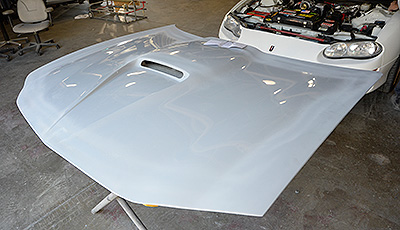
The RKSport hood came out of the box
nearly ready to paint. Image: CHpg
Staff. |
|
 |
|
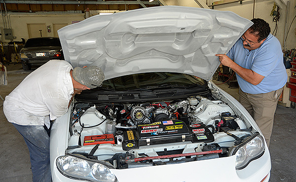
Before any significant finishing work
was done, the guys at Diamond Finish
Auto Body, test fitted the hood on the
Tom Henry RS.
Image: CHpg Staff. |
Besides the look and
how they are made, another reason we picked the RKSport
hood is the cold air ducting inside the O.E. SS hoods is
reproduced on its underside. The hood scoop is
functional with incoming cold air split between two
ducts which channel air to the our Whisperlid air filter
top.
|
 |
|
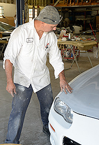
The test fit confirmed RKSport's
"first-time-fit". Image: CHpg Staff. |
|
The final work on the
Tom Henry RS was done at THR's West Coast development
facility so we had RKSport ship the hood to our bodywork
specialist, Diamond Finish AutoBody in Santa Barbara,
California, for installation and painting.
At Diamond Finish,
during a test installation before any sanding, we found
the fit of RKSport's reproduction of the SS Hood to be
quite good. The only significant difference came at the
left front corner of the panel. To get the panel gap
correct at that spot, we had to shim the left side of
the front fascia up about an 1/8-inch. The RKSport hood
is not drilled for the stock hinges' locating tabs.
While ten minutes with a drill will fix that, we asked
Tom Baker why there were no holes for the tabs. He told
us that if one bends the tabs on the hinges flat, the
rear of the hood has a much greater range of adjustment
as to its position in the hood opening, so they leave
the tab holes undrilled figuring installers will do that
and have more adjustment–smart guys at RK Sport. |
|
 |
|
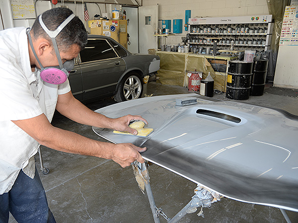
A small amount of sanding and priming
was done to the edge of the hood at the
front. Image: CHpg Staff. |
|
 |
|
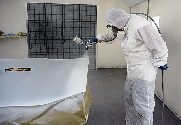
After that, it was into Diamond Finish's
spray booth for a coat of white and then
a clear coat. Image: CHpg Staff. |
The crew at Diamond
Finish sanded and primed the hood then shot it with
Arctic White. After painting, the hood was installed
using the lower pressure struts RKSport includes with
the hood. A laser-cut, polished, stainless steel grille,
also, comes with the hood and is installed over the hood
scoop opening. The polished stainless didn't look good
on a white car with a black front grille insert so, we
had our long-time coating vendor, Extreme Performance
Heat Coatings, put a satin black coating on the grille.
|
 |
|
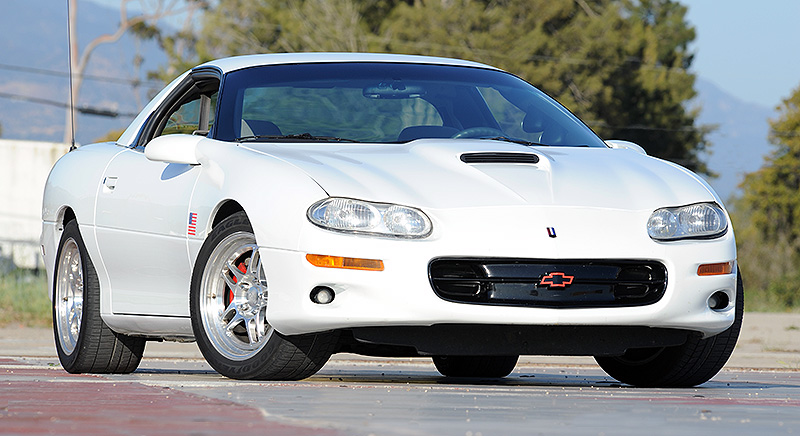
Not only did the RKSport Competition
Hood do much to toughen the THRS's look
but its functionality was shown in our
road testing. Image: CHpg Staff. |
|
 |
|
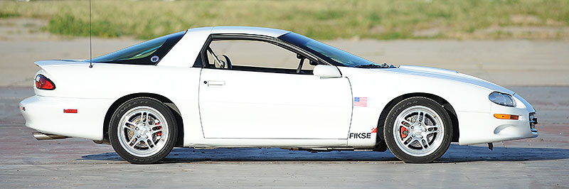
In fact, the Tom Henry RS came out
looking "tough" from just about any
angle. Image: CHpg Staff. |
For-Real Ram Air
With the new hood, I
decided to retest with the wideband O2 to see if the
hood made any difference in airflow into the engine.
Oh boy, did it ever!
I was astonished to
find that at highway speeds, the RK Competition Ram-Air
Hood increases air flow through the MAF sensor by 5-6%.
In fact, I had to, once again, tune the high end of the
MAF table in the calibration because, at high throttle
openings the engine went lean–Lambda .89-.92. Once we
did that, the WOT air:fuel was back at the ideal
.85-.86λ we like to see. Too bad we can't properly
duplicate the airflow into that hood on the chassis
dyno. I'd love to see how much of a change in power
output that hood is worth.
|
 |
|
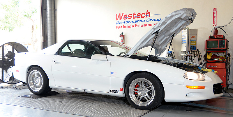
After the hood installation and some
final cal work, it was back to WesTech's
Superflow Chassis dyno. Image: CHpg
Staff. |
Back at Westech
Performance Group for some final numbers, it was hot
day. As knock retard hedge, I added enough Rockett Brand
100 Unleaded to bump the octane to 93. In three runs on
Westech’s AutoDyn, we were at 0.84-0.87 λ. We, also,
made our best SAE-corrected, rear-wheel power and torque
yet: 244.9-hp@5750-rpm and 234.5lbs/ft@4700-rpm,
SAE-corrected. That is just under 17-rwhp and 14-rwlb/ft
torque more than we did in our last chassis dyno test in
Part 5–a significant improvement. Using a .82 correction
for driveline loss, that's about 299-hp and 280 lbs/ft,
SAE, at the flywheel. Not bad for a 3.8-liter V6 which
started at 200-hp.
Next, we ran some
quarter-miles at our test venue. We use a Vericom VC3000
Performance Testing Computer to measure the car’s
performance. Vericoms have three major components: an
accelerometer, a crystal clock and a microprocessor. The
first two measure acceleration and elapsed time and the
third calculates velocity every 1/100 second. Knowing
the velocity and the time enables the VC3000 to
calculate distance every 1/100 second.
Suction cups or, for
some models more powerful vacuum cups, attach a Vericom
to the windshield. It can be installed in less than a
minute. It runs on an internal battery or off the car
battery via a 12-volt power cord. An “OBD2” cable is
available so the Vericom can recored engine controls
data along with vehicle dynamics data.
The VC3000’s accuracy
and dependability is such that it is used as a braking
test device in traffic accident investigations
worldwide. Vehicle manufacturers, tire companies, law
enforcement, transit companies and training academies
all use them. Vericoms are approved by the Federal
Aviation Administration to measure runway friction. A
test of a runway’s traction–or lack thereof– is
information required for pilots of commercial aircraft
landing in bad weather. Vericoms are widely used in the
United States for that purpose.
The unit’s accuracy
is 1% in time, g-force, speed and distance. In
acceleration testing, the difference between a Vericom
time and drag strip clocks is typically .2 to .4 sec.
and comes from the VC3000 not having a “roll out” delay
before timing begins. The later model of the Vericom,
the VC4000, does, in fact, have a “roll-out correction”
which defaults to 12-inches but can be user-adjusted for
other values.
With the Vericom in
the Tom Henry RS we headed for our test venue. In three
quarter mile passes, we averaged 15.22/96.90. To equate
that to drag strip timing, we’ll subtract .3 sec. for
the lack of roll-out to get: 14.92 No doubt, if we were
going to do another part of the series, we'd trade the
stock 3.23 axle ratio for a set of 3.73s then put some
drag radials on and have a 13-second car.
Finally, we took the
Camaro to a California Smog Check station and had it
tested. The engine tested clean by a significant margin.
Spray
The Tom Henry RS's
final engine modification was nitrous oxide injection
from Mike Thermos' Nitrous Supply. We installed a
"Sportstar Universal EFI Dry Manifold Kit" (PN NS06100)
and a "WIde Open Throttle Switch" (PN NS25633). The
Nitrous Supply Dry Manifold Kit is for engines with
electronic throttle control and a vacuum-controlled,
return-type fuel system, however, because this kit is
not specific to a V6 Camaro, there were extras–mainly
fasteners, some 3/16 fuel hose, an extra 7-ft. of AN-4
nitrous hose and fittings–necessary to get it working.
With the Sportstar
Kit, nitrous is injected just downstream of the throttle
body's MAF sensor. Extra fuel is supplied through the
injectors by increasing fuel pressure when the system is
active.
|
 |
|
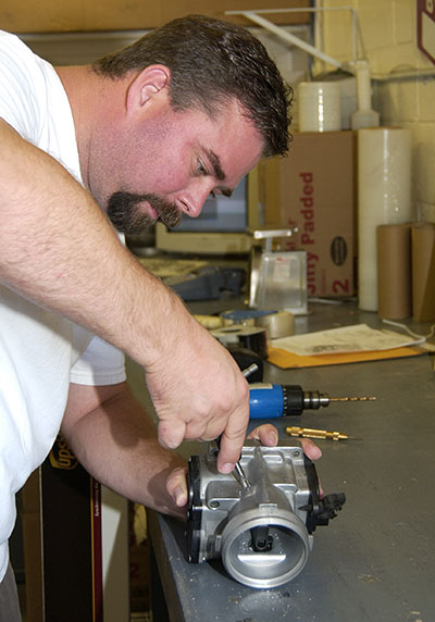
Nitrous Supply's Mike Flynn at work on
our throttle body. If you are very
careful, nozzle mounting can be done
with a hand drill. The TB material is
thin so, to ensure the nozzle doesn't
back out, use a thread locking compound
such as Permatex Medium-Strength
Thread Locker Gel. After nozzle
installation, thoroughly clean the TB to
eliminate any metal chips. Image: CHpg
Staff. |
|
 |
|
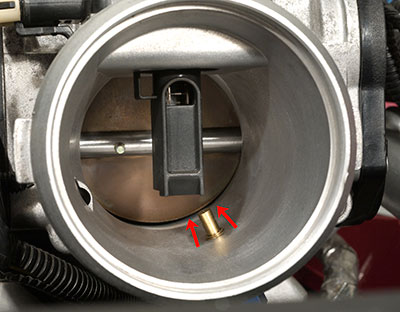
It's critical that the nozzle point to
the rear of the TB. If it does not,
nitrous oxide can "bounce" off the sides
of the throttle body, causing errant
mass air flow sensor readings resulting
in significant problems with fuel
delivery. Take a fine-point Sharpie,
mark a line on the top of the nozzle
then tighten the nozzle until the line
points to the rear. Image: CHpg
Staff. |
The discharge nozzle
has to be installed in a specific spot in the throttle
body. While it is a task which can be accomplished by a
DIY with a drill press, we decided the job was better
done by Nitrous Supply. We pulled off the throttle body,
visited Nitrous Supply and had Mike Flynn install the
nozzle. Inside the discharge nozzle is the nitrous jet.
|
 |
|
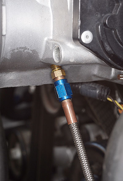
Nitrous nozzles have SAE 37° AN04
connections to which our braided
stainless steel covered Teflon hose
attaches.
Image: CHpg Staff. |
We put the nitrous
oxide cylinder in the cargo well behind the rear axle.
Using some wood we bought at Lowes and the two bottle
brackets that come with the kit, we built a mount which
held the bottle securely but could, also, be easily
lifted out when the space was needed for cargo. Our
bottle holder accepts either 10-lb or 15-lb Nitrous
Supply cylinders. The positioning of the bottle in the
brackets is key to optimal performance.
|
 |
|
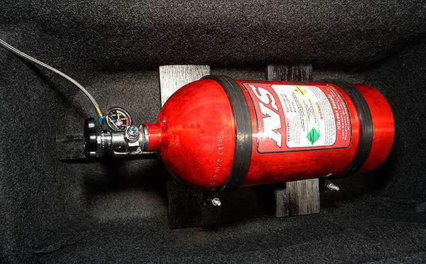
We built a wooden frame, painted it flat
black, bolted Nitrous Supply bottle
mounts to it and viola–a removable
nitrous bottle mount which fits nicely
in the Camaro's cargo well. We installed
the Nitrous Supply 10-lb bottle into the
mounting rings. Image: CHpg Staff. |
Under pressure,
nitrous oxide is a liquid. A nitrous bottle is made such
that its siphon tube extends to a point on the bottom of
the bottle opposite the center of the label. The idea is
to orient the end of the siphon tube such that
acceleration keeps the end of the tube covered with
liquid nitrous oxide. On a bottle, such as ours, located
perpendicular to the vehicle centerline with the
discharge valve on the driver side of the car, orient
the label so it is 30° from vertical towards the front
of the car. That puts the pick-up end of the siphon
tube, 30° towards the rear from the lowest point of the
bottle.
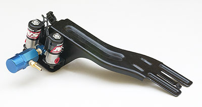
Next, we assembled
the "solenoid module" by installing a Nitrous Supply
solenoid on each end with the solenoid tee and the
nitrous pressure regulator in the center. We screwed the
solenoid module to the bracket that comes with the kit
and mounted that on the driver side, front subframe
rail, above and just behind the front stabilizer bar
mount.
|
 |
|
We used the stock power steering
reservoir bracket to hold the pair of
Nitrous Supply solenoids and the
regulator. Image: CHpg Staff. |
|
 |
|
This is the solenoid/regulator assembly
once the power steering reservoir
bracket is reinstalled on the left front
frame rail. Image: CHpg Staff. |
We ran the AN-04
braided stainless-steel-covered Teflon hose from the
solenoid module, along side the fuel and brake lines
which run down the driver side of the floorpan, to the
back of the car. In several places, we attached the hose
with zip ties. In places where this nitrous feed line
runs near our headers, we insulated it with Design
Engineering Heat Sheath (PN 010419). The hose included
with the kit was not long enough, so we added a Nitrous
Supply, four-foot, AN-04 extension. To get the hose into
the cargo bay, we temporarily removed one of the two
plugs in the bottom of the cargo well and ran the hose
through the hole. To keep the sharp metal edges around
the hole from cutting the hose, we sliced a three-inch
piece of plastic hose from our scrap bin lengthwise and
slipped that over the AN-4 where it touches the edges of
the hole. We removed the screw holding the left corner
of fuel tank's aluminum shield, tucked the nitrous hose
into the void between the tank and the shield then
replaced the screw. Finally, we dropped our custom-made
nitrous bottle mounting in the well and connected the
nitrous hose.
The Nitrous Supply
Sportstar EFI Kit is known as a "dry system" because
only nitrous oxide flows into the throttle body and
extra fuel comes through the fuel injectors. To meter
that extra fuel, nitrous oxide at greatly reduced
pressure, is fed to the stock fuel pressure regulator
(FPR) which causes fuel pressure to rise from the
approximate 50 psi normal for a 3800 V6 to 65-70 psi.
|
 |
|
We mounted the Nitrous Supply "WOT box"
on top of the driver-side wheel house
just behind the underhood fuse block.
Image: CHpg Staff. |
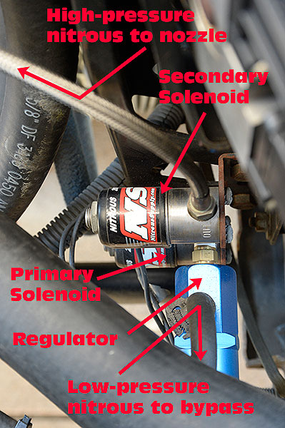
The reduced nitrous
pressure fed to the FPR is accomplished in two steps.
The first takes place in the nitrous regulator between
the two solenoids. From the nitrous regulator, we ran
fuel injection hose across engine compartment behind the
cooling fans then, up to the top-right-front of the
engine and along the right rocker cover to the rear of
the engine. We installed the Nitrous Supply pressure tee
into the hose which runs from the intake manifold,
around the back of the intake plenum to the fuel
pressure regulator. The tee comes with a .042-in. jet in
it which bleeds off some of the nitrous flow from the
nitrous regulator, further reducing the pressure applied
to the FPR. The size of this jet can be varied to change
the air:fuel ratio when nitrous is flowing–smaller jet,
more fuel pressure; bigger jet, less fuel pressure.
The pressure on the
FPR generates more fuel flow, provided the fuel system
has been modified for adequate flow at the higher
pressure level and we accomplished that with the
Racetronix fuel pump (PN PN F99-FPKG-2) installed for
Part 4 of this series. Some DIY's don't understand the
relationship between fuel pressure and fuel pump
capacity. If you raise the pressure, the pump's fuel
flow limit decreases. If that decrease goes below the
engine's greatest required fuel flow, the engine will go
lean at high rpm. We raised the the engine's need for
fuel flow through our engine mods, then we raised the
system pressure. That overtaxed the stock fuel pump.
Hence our switch to a Racetronix.
|
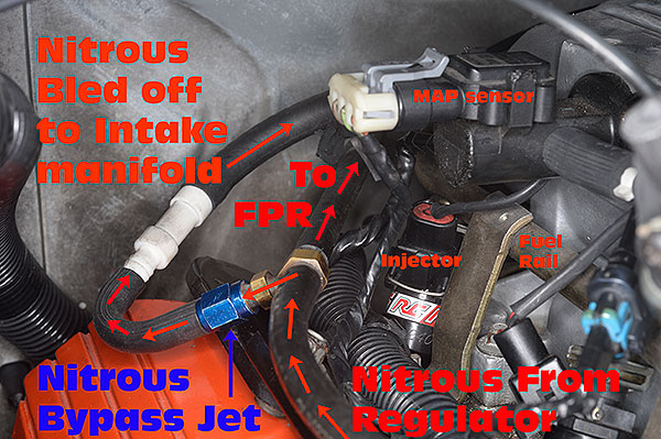 |
|
The plumbing of the nitrous bypass and
the fuel pressure regulator gets a
little bit complicated but the system
works quite well provided the fuel
system is capable of the extra flow the
nitrous oxide system requires. Image:
CHpg Staff. |
Any nitrous oxide
system uses a relay to control the solenoids and Nitrous
Supply's system includes a 30-amp relay which we mounted
on the front of the inner fender. We wired the load side
of the relay to the battery and the solenoids.
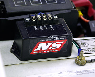
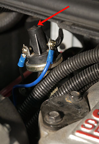
We attached the
Nitrous Supply Wide Open Throttle Switch–"WOT box" for
short–on top of the left inner fender. It triggers
nitrous injection for an engine without a mechanical
throttle linkage by sensing throttle position sensor
(TPS) voltage and energizing the nitrous solenoid relay
just before maximum TPS. This voltage varies depending
on the engine. Using our shop's Fluke 88V DMM we
measured the TPS #1 voltage at wide open throttle and it
was 3.30-3.32v, so we adjusted the WOT Box to kick the
primary nitrous solenoid on at 3.28v. Finally, we
connected the box's output to the line side of the
nitrous relay.
Next, we removed the
cap from the fuel rail's fuel pressure connection. Then,
using a tire valve core tool, we took out the Schrader
valve core. Once the cap and valve were gone, we
installed the nitrous kit's extension tube, which adapts
the kit's fuel pressure safety switch to the AN-04
connection on the fuel rail, and screwed the switch in
place. Finally, we wired the fuel pressure switch
between the secondary solenoid and ground and routed the
switch wires along side to the hose running down to
nitrous regulator. When the system is energized, the
primary nitrous solenoid opens and nitrous oxide flows
through to the nitrous regulator and up the hose to the
tee and to the FPR. When the fuel pressure rises to 65
psi, the safety switch closes energizing the secondary
nitrous solenoid which opens, allowing gas to flow to
the discharge nozzle and into the throttle body. The
fuel pressure switch prevents nitrous oxide flow until
adequate fuel pressure exists.
|
 |
|
The Nitrous Supply fuel pressure safety
switch is installed in place of the fuel
pressure test connection on the end of
the passenger side fuel rail. If you
remove a rubber plug on the top of the
switch, you can adjust its trigger
pressure with a hex key. The default
setting is 50 psi, but it must be
readjusted to turn-on 3-5 psi above a
V6's nominal fuel pressure range of
48-52 psi. The best way to do this is
test the engine's fuel pressure per the
Service Manual, then use a calibrated
air source to set the switch 3-5 psi
above the pressure you read. Image: CHpg
Staff. |
Nitrous Supply
includes a generic toggle switch for arming the system,
but we decided a neater installation would be a second
fog light switch (PN 10273879) in the panel above the
radio as an arming switch. We ordered one from the Tom
Henry Racing parts department, removed the plug
originally in the panel and popped the switch in place.
After that, we installed a push button, momentary switch
on the gear shift lever just below the shift knob and
positioned such that when the driver's hand is on the
knob, he can flick a thumb down and push the button.
We ran a hot wire
from the fuse panel to the master switch, then to the
button and from there, though the fire wall to the WOT
box. To get nitrous, the arming switch must be closed,
the throttle must be wide open, the driver must push the
button and the fuel pressure needs to be up.
|
 |
|
These are the features we like in the
Denso Iridium Power spark plug. Image:
CHpg Staff. |
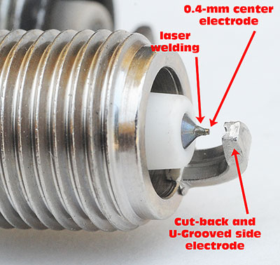
The last step in
preparing the car for nitrous was to install a fresh set
of Denso Iridium Power IT-20 spark plugs. We've used
Densos since the start of the Tom Henry RS series. We
like the Iridium Power design because it's a combination
of the best of Denso's two product lines, the
iridium-tipped plugs it makes for car companies–General
Motors being one of them–and its track-proven racing
plugs. A key feature of this Denso is the small, 0.4-mm
iridium center electrode. The advantage of an iridium
electrode over one made from more traditional platinum
is better durability and lower resistance. Another
obvious characteristic of the Denso is its ground
electrode which is cut-back, tapered and grooved. The
small center electrode and unique shape of the ground
electrode give the spark maximum exposure to the
incoming, air/fuel charge. In short, we think the IT-20,
which is a heat range colder than stock, is the best
spark plug choice for 3800s in street high-performance
and mild racing applications. For track only
applications, we'd use the even-colder, IT-22.
With all this nitrous
hardware installed, it was time to take the car out for
a little test run. Did it work? Damn right! When we
shifted into second gear, then squeezed the button–boom!
We got a serious, nitrous-fortified, kick in the ass.
The next step was to
verify the tuning of our newly installed Nitrous Supply
system. Testing with the Innovate Motorsports LC-1 found
that when the nitrous was working, the engine was a bit
rich–0.73-0.76-λ so–with some tuning, the nitrous hit
would be even bigger.
 |
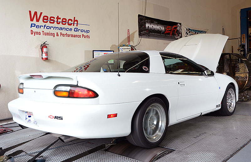
|
One more time on the WesTech dyno, this
time with spray, had us just short of
400-hp. Image: CHpg Staff. |
We decided the
nitrous flow was likely adequate but, because the
air:fuel was rich we weren't getting the full benefit.
We needed to lean the engine out to the 11 or 11.5:1
suggested by Nitrous Supply and, with the Nitrous Supply
Sportstar EFI system, you can do that by decreasing fuel
flow during nitrous operation.
First thing we did
was test what kind of fuel pressure we had when the
nitrous system was enabled. We installed our Waekon
digital fuel pressure tester (PN 48165) and went for a
road test. When we squeezed the nitrous button
and–wow–97-psi fuel pressure! No wonder the engine was
rich on the bottle.
With the nitrous
oxide system operational, additional fuel flow comes via
higher-than-atmospheric-pressure applied to the FPR
diaphragm. The size of the jet in the tee determines
that pressure. Ideally, you want the air:fuel ratio with
the nitrous system operating at about 0.80-lambda. That
is a little rich, but you need that richness to
compensate for inconsistent distribution of nitrous
oxide in the intake manifold.
We started by
doubling the diameter of bypass jet to .081-in. Fuel
pressure was still too high. We went up to .091-in. and
finally to .110-in. Fuel pressure was now at 70-lbs.
Air: fuel with nitrous oxide working was finally
hovering around .79-lambda.
We rolled the Tom
Henry RS on Westech's Superflow Autodyn for the final
time. Because the engine with nitrous oxide being
injected is more prone to detonation, we put a 2:1 mix
of Rocket Brand 100-oct Unleaded Racing Gasoline and
pump gas in the tank and let fly. On nitrous, the car
made 316.3 hp at the wheels at 5775-rpm and 325.8 lbs/ft
at the wheels at 3630-rpm, SAE-corrected. Those numbers
work out to 385-hp and 401 lbs/ft torque, SAE at the
flywheel. A 75-shot indeed! Actually, it's an "85" shot
and more than enough nitrous oxide for an engine with a
stock pistons and rings. Peak torque moving down 1000
rpm is a function of the increased cylinder pressure in
the mid-range which nitrous oxide can provide.
|
 |
|
Image: CHpg Staff. |
Once again, we
installed our Vericom VC3000 and did some more
quarter-mile tests. With nitrous, the our Camaro went
13.65/100.43.
|
THRS Chassis
dynamometer test history
Rear wheel power,
SAE-corrected |
|
1) 162.3-rwhp–Stock
|
|
2) 173.5-rwhp–Stock
with Flowmaster exhaust |
|
3) 206.0-rwhp–DeGroff
ported big-valve heads, Comp Cam, Extrude Honed intake,
Extrude Honed stock exhaust manifolds, Flowmaster
exhaust, Z-Industries reprograming. |
|
4) 212.9-rwhp–DeGroff
ported big-valve heads, Comp Cam, Extrude Honed intake,
Dawson Headers, Flowmaster exhaust, Z-Industries
reprograming. |
|
5) 219.1-rwhp–DeGroff
ported big-valve heads, Comp Cam, Katech Valve Springs,
Extrude Honed intake, 1.8 rockers, Dawson Headers,
Flowmaster exhaust, Z-Industries reprograming. |
|
6) 228.3-rwhp–DeGroff
ported big-valve heads, Comp Cam, Katech Valve Springs,
Extrude Honed intake, 1.8 rockers, Dawson Headers, 3"
cat converter and S-pipe, Flowmaster exhaust,
Z-Industries reprograming. |
|
7) 244.9-rwhp–DeGroff
ported big-valve heads, Comp Cam, Katech Valve Springs,
Extrude Honed intake, 1.8 rockers, RC Engineering
injectors, Dawson Headers, Flowmaster exhaust, in-house
reprogramming. |
|
8) 316.3-rwhp–DeGroff
ported, big-valve heads, Comp Cam, Katech Valve Springs,
Extrude Honed intake, 1.8 rockers, RC Engineering
injectors, Dawson Headers, Flowmaster exhaust, nitrous
oxide, in-house reprogramming. |
Farewell to the
THRS
Clearly our Extrude
Honed intake manifold, RC Engineering injectors, Mark
DeGroff heads with Manley Valves, Comp Cam, Katech Valve
Springs, Dawson Headers, Flowmaster exhaust, our ECM
programming and the hardware from Nitrous Supply all
work very well.
After five years,
it's time to turn-off the lights and shut the door on
the Tom Henry RS. We've learned a lot about how to
improve performance and tune a 3800 Series II V6 for
high-performance street use and modify the fourth-gen
Camaro chassis for better handling and braking. We hope
you have too.
If you enjoyed this
series, let us know. If we hear from enough readers, we
might do an encore. Finally, we'd like to thank all of
our project sponsors for their support of the Tom Henry
RS project.
Project Sponsors:
|