|
Building the Tom Henry RS
Pt 2: Heads and Valvetrain
|
 |
|
Image: CHpg Staff. |
|
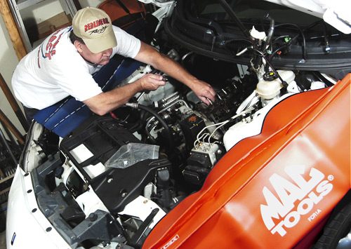
In the first part of this series, a Flowmaster exhaust,
SLP 1.8:1 rockers and other, minor bolt-ons, gained us
17-hp at the wheels. Clearly, our V6 Camaro's response
to mods is promising and there's potential in the 3800
Series II engine, so now, we're going to get more
serious about performance enhancement.
Get that 2010 Feeling
One reason we're modifying the engine in the Tom Henry
RS is, as stated previously, to use our '01 Camaro's hot
rodded powertrain to attempt to simulate the performance
of the 5th Gen, 2010 Camaro which will sell the most: the
entry-level V6.
The obvious base engine for '10 is a further-developed
version of GM's "Global V6 Engine" which, in it's "3.6L
V6 VVT" version, is new this year in a number of GM
passenger cars including the Pontiac G6, the Cadillac
CTS and the Holden VE Commodore, and ranges from
255-275hp.
|
 |
|
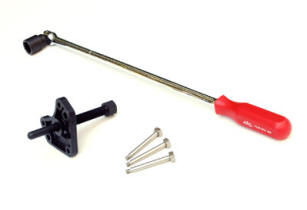
These tools remove the 3800's harmonic
damper. On a five-speed car, lock the driveline with a
big screwdriver. Really lean on that breaker bar and the
bolt will loosen. With the bolt out, you still need a
puller to get the damper off. The Kent-Moore puller
works best, but others may, too, if you use 5/16x1
bolts. Longer bolts will break the trigger wheel on the
back of the balancer. When replacing the balancer bolt,
use the same killer breaker bar but with a torque angle
meter and tighten the bolt to 111 ft/lbs plus 114°.
Yep–that's tight. Image: CHpg Staff.
|
|
With the Tom Henry RS project, our goal is 260hp. The
3800 Series II, four times listed on the annual "Wards's
10 Best Engines" list in the late 1990s, has an ideal
foundation for our project because its short block was
designed with a 260hp supercharged application (still in
production at GM, today) in mind. To meet our goal, we
won't need to do anything to the block, crank, rods or
pistons. Our mod'ing will be confined to the camshaft
and the top end of the motor. We'll begin by porting the
heads, installing bigger valves and changing the cam.
Do-it-yourselfers can handle the tasks discussed here,
but some will be challenging. While most of those tough
jobs can be completed with tools advanced DIYs possess,
you'll need a few special items. To remove the
crankshaft balancer bolt requires a 2-foot Breaker Bar
and a 15/16 in. impact socket and, again, we chose Mac
Tools products (PN VF24FAPA and PN VP306R). |
The cam change requires an SPX Kent-Moore Power Steering
Pulley Remover (J-25034-C), Crankshaft Balancer Remover
(J-38197-A) and a Front Cover Seal Installer
(J-35354-A). An inch-pound torque wrench such as the Mac
Tools, 0-150 in/lb. unit (PN TWDFX150N) comes in handy
during reassembly of some of the small fasteners used to
hold intake parts. Required for head bolts, the harmonic
damper bolt and other fasteners is a torque angle meter
and we got that (PN TM281) from our Mac man, too.
You need service data and the best is in the
Camaro Service Manual
for your model year. A lower-cost alternative is the
1993-2002 Camaro Haynes Repair Manual
but instructions in it are very condensed and have a few
errors.
If you're working along with us, you know it's a vicious
rumor that modern GM engines use all metric hardware.
You'll find a mix of metric and fractional fasteners
because the 3800's distant ancestor is the 231 cubic
inch Buick V6, designed a generation ago, before the
industry's metric conversion was complete.
Ok. Let's get to work
|
Off came ignition hardware, EGR pieces and miscellaneous
bracketry. Using fuel line disconnect tools in a
Kent-Moore
"Port Fuel Injection Diagnostic Kit" (PN
J-37088-A),
we disconnected the fuel system, removed the rocker
covers and pulled the valve gear. We detached the drive
belt tensioner assembly, removed the fuel rail, lifted
the upper and lower intake manifolds and removed the
power steering pump pulley but left the pump mounted on
the block. Finally, we got the exhaust manifolds off and
removed the heads. To avoid the tedious job of removing
the ignition mounting bracket from the left head, remove
the head with the bracket in place, then once you have
the head sitting on the bench; remove the bracket. |
|
 |
|
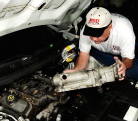
Tear down the engine with
care. If you're not good at remembering
where stuff goes, mark or tag fasteners.
Same is true of wiring harness plugs and
hose connections. A clean engine is a
happy engine so, washing and (where
necessary) painting parts is something
we learned to love.
Image: CHpg Staff |
|
Next to come off was the harmonic damper, one of the
challenging tasks mentioned earlier. The damper is a
modest press-fit on the crank snout but its bolt is
about 3/4" in diameter with a 15/16" hex and is
incredibly tight. A 3/4-drive, or very powerful
1/2-drive, air impact wrench fitted with a 15/16" impact
socket will break it loose but, to make room for that,
you need to remove the front stabilizer bar. For us, it
was easier to put the 15/16" socket on a Mac Tools
breaker bar, brace our feet on the right front tire and
really pull on the breaker bar. That broke the bolt
loose, but it took every bit of strength we could
muster.
We slipped off the balancer then disassembled the
crankshaft position sensor and its shield. Some non-GM
shop manuals imply that you leave the oil pan alone when
pulling the front cover. Not. Remove the front three pan
bolts and loosen all but the two rear bolts by a quarter
inch or so. That drops the front of the pan enough to
separate its gasket from the front cover. Pull the cover
forward, off its dowel pin, then up and away. Next, we
removed the timing chain tensioner, chain and sprockets,
lifters and took out the cam.
Pay no attention to non-GM manuals which say that, to
change the cam, you remove the fans, radiator and air
conditioning condenser which forces an A/C recharge.
With our '01 Camaro, we got the cam out without all that
work and it wasn't difficult. Other model years might be
the same way.
Cylinder Head Prep
|
For head work on the Tom Henry RS project, we chose Mark
DeGroff's Cylinder Head Service and Machine Shop in
Northridge, California. First, DeGroff's Kent Grodske
disassembled the heads and examined all parts for
unusual wear. There was none, so Grodske gave the head
castings a good session in the wheel abrader and
then in the solvent tank followed by a blow-dry.
Next came a magnetic particle inspection of the
castings looking for cracks, especially around
the exhaust valve seats.
|
 |
|
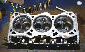
One of our 3800 Series
II heads, stripped-down and ready for
the solvent tank.
Image: CHpg Staff. |
|
|
 |
|
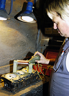
At Mark DeGroff's Cylinder Head Service, Ken
Grodske performs a magnetic particle inspection. The
horseshoe device generates a magnetic field. Ken
sprinkles metal powder on the casting. If there's a
crack, the powder forms a pattern over it.
Image: CHpg
Staff.
|
|
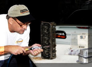
Before we cut Mark DeGroff loose with his porting tools,
we hauled the bare heads back to our shop for some
preliminaries. Using some carbide burrs (PN 46067) we
got from the Eastwood Company along with various
cartridge rolls and rotary stones from a Standard
Abrasives Head Porting Kit (PN 260001), we enlarged,
then deburred the pushrod passages in the heads which
double as oil return passages. The point of this was to
improve oil return to the pan. Then, we deburred and
detailed the exterior of the castings.
|
 |
|
To enhance oil drainback, using Standard
Abrasives Motorsports Division products, we enlarged and
deburred the heads' oil return passages. Then, we
lightly deburred their exteriors. Any cylinder head
performance upgrade would include those steps.
Image: CHpg Staff. |
|
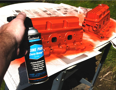
Finally, we spayed the castings with brake cleaner,
wiped them down with Eastwood "Pre" paint prep spray (PN
10041Z) and dried them with shop air. To further enhance
oil return, we painted the tops of the heads and the
pushrod/oil return holes with Eastwood Gyptal (PN
46000Z). We stuck the valve covers on to mask-off what
we'd just done, then shot the exteriors with Eastwood
Chevrolet Orange (PN 10016Z). After an overnight drying,
we took the heads back to DeGroff's. |
Mark's first order of business was to flow test the O.E.
intake and exhaust ports. He installed stock valves back
in one of the chambers and tested the ports on his
Quadrant Scientific FlowLab 520, flow bench. From .200
to .500 in. valve lift, the stock intakes flowed ok,
but, below .200" and above .500", they needed work.
|
Now it was time to set goals for our 3800 cylinder head
project: significant flow improvement below .200" lift
and between .500" and .600" along with a modest
improvement between .200" and .500". To reach those
targets, Mark DeGroff developed a five-point strategy:
1) machine the seats for the bigger valves, 2)
port/polish the spaces just above the valve seats, 3)
modestly enlarge and polish the intake and exhaust
ports, 4) unshroud the valves, and 5) do a multi-angle
valve job.
|
|
 |
|
The guys at Tom Henry
Racing have painted a lot of engine
parts in their days. Eastwood makes some
of the best engine paints we've used. On
a clean part, 2-3 coats of Eastwood
engine paint will last for many years.
Image: CHpg Staff. |
|
Stock valve sizes are 1.80" intake, 1.52", exhaust. You
can install larger valves in 3800 heads, but you're
limited by the induction hardened exhaust valve seats,
part of which are machined away during the process. The
largest exhaust which usually maintains acceptable seat
durability for long-term street use is a 1.57 and a 1.55
is probably safer. With a 1.55 exhaust, a 1.90 intake is
plenty big, if valve proportion is to remain .80-.85,
however, intakes up to 1.97 in. can be used if exhausts
are held to 1.55. We decided on a 1.90". intake and a
1.55". exhaust.
|
 |
|
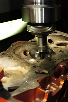
The first step in a DeGroff Port/Polish is to
rough machine the seats for larger valves. This seat
gives Mark a reference point from which to port the
bowls. Image: CHpg Staff |
|
Like many modern vendors of cylinder head preparation
work, DeGroff's Head Service uses a Serdi "Valve Seat
and Guide Machine", specifically a Model 60, to machine
seats and guides. The Serdi advantage is more accurate
machining of those parts of the head. The first of three
sessions for our heads on the Serdi was to rough-cut the
new, larger valve seats which would give Mark DeGroff a
"reference point" to use during the initial enlargement
of the ports just above each seat. Because of their
shape, head porters call these spaces "bowls".
In addition, with our heads getting not only bigger
valves, but multi-angle seats, there is a time savings
in that, with the Serdi, DeGroff could enlarge the seats
and rough-cut the seat angles at the same time. Lastly,
Mark unshrouded the intake valve by taking a light cut
out of the adjacent chamber wall. |
"Bowl work" is a time-honored staple of the head
porting craft. Using a carbide burr along with Standard
Abrasives cartridge rolls, DeGroff enlarged and
contoured the bowls. The intake valve guide bosses were
smoothed and the exhaust guide bosses were removed.
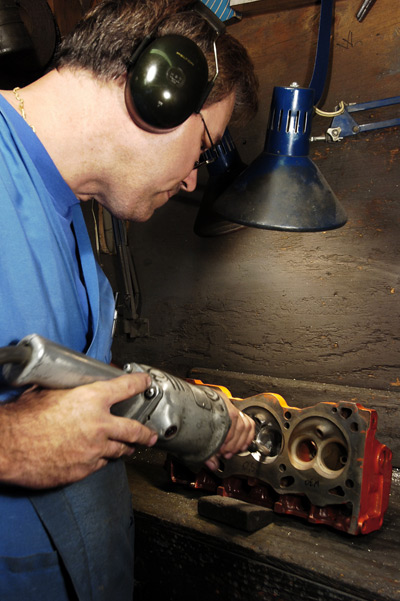 |
|
Bowl-work. Yeah, it's time consuming, but it's
where the air flow is. Mark DeGroff, a bowl-work wizard,
indeed, is at work with the high-speed grinder fitted
with a carbide burr. He's doing preliminary modification
of an exhaust bowl which brings the valve throat to a
diameter appropriate for the new, bigger valve and
cleans-up the rest of the bowl. |
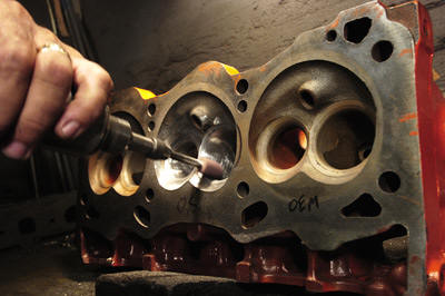 |
|
After the rough bowl work is done with an
Eastwood carbide rotary file, Mark switched to Standard
Abrasives' cartridge rolls to do the finishing work on
the bowls and the chamber walls. Image: CHpg Staff.
|
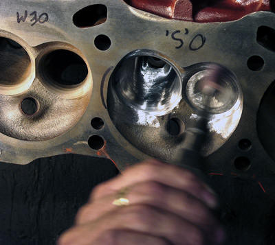 |
|
When doing the chamber, use old valves to
prevent nicking-up the valve seat area. Image: CHpg
Staff. |
Using Fel-Pro intake gaskets (PN MS95809-1) as a
template, DeGroff enlarged the intake port entries then
ported the intakes down to the bowls. He enlarged the
exhaust ports from the bowl to the port exit in the
head.
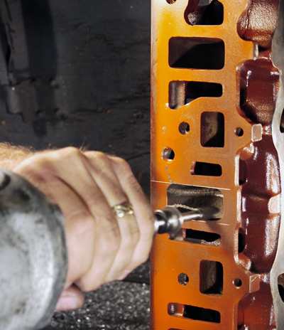 |
|
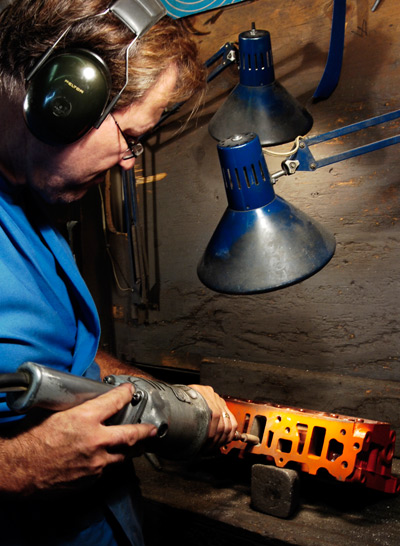
Initial porting of the intake
port entry area is done with a rotary file.
The outline of the port is scribed on the
gasket flange, then the port is opened up to
that size. Sure, you can go larger, but
there'd be little advantage with a street
hi-po motor like our V6.
Image: CHpg Staff. |
 |
|
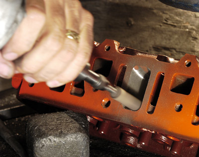
Bright lighting and a
high-speed grinder is essential for good
port work. Either an electric or an air
grinder work well as long as they have a
1/4" chuck. You cannot use a drill motor for
porting. Image: CHpg
Staff. |
 |
|
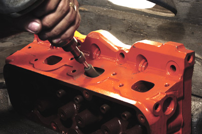
Once the rough work is done,
switch to cartridge rolls to finish the
port. Image: CHpg Staff. |
 |
|
The exhaust port exits are done in a manner
similar to the intakes. Image: CHpg Staff.
|
The "short-turn" or "short-side" radius is the holy
grail of cylinder head airflow. It is where the floor of
the port turns downward to the area of the valve seat
closest to the port entry. There may be differing
opinions amongst cylinder head experts about some
aspects of porting, but one issue upon which they all
agree is the importance of the short-turn radius. The
stock heads are really terrible around their short-turn
radii so DeGroff spent a lot of time on the tops of the
bowls and how that area blends, through the short turn
radius, to the port floor.
At this point, we stepped in and assisted DeGroff with
the remaining grunt work: polishing the ports and the
chambers with Standard Abrasives Flap Wheels and
Cross-Buffs.
 |
|
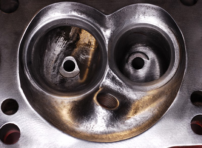
If you were sitting on the piston
top, this is what the chamber on a finished DeGroff head
would look like. Image: CHpg Staff. |
 |
|
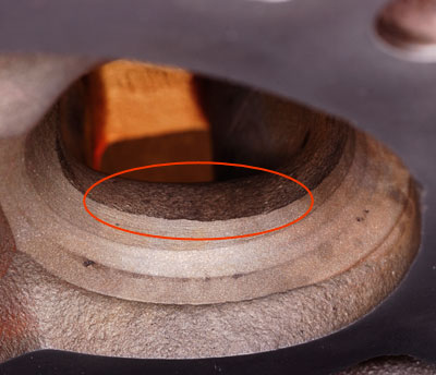
The short-turn radius (inside the red) of the
stock head. Look at that nasty ridge, just above the
valve seat. Man, that's bad. Image: CHpg Staff. |
 |
|
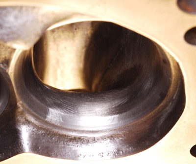
The same spot after DeGroff and our helper got
through with it. Looks pretty cool, huh. It works even
better than it looks. Image: CHpg Staff. |
 |
|
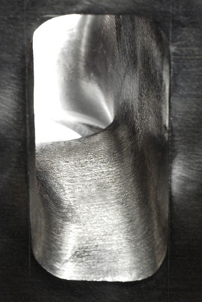
This is the floor of the same port, shot from
the other end, showing how the port floor blends
smoothly into the start of the short-turn radius. Image: CHpg Staff. |
 |
|
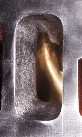
A stock intake port entry. Image: CHpg Staff. |
 |
|
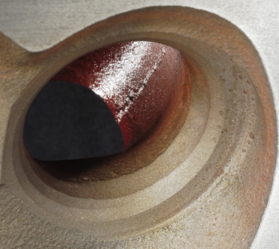
Same port entry, after our port/polish work.
Image: CHpg Staff. |
 |
|
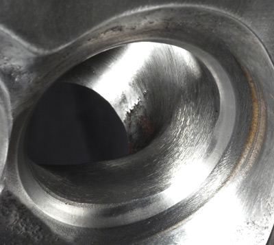
The stock exhaust seat and bowl–same ratty
looking ridge just above the valve seat. Image: CHpg
Staff.
|
 |
|
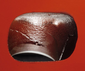
The much better exhaust seat and bowl. Image: CHpg Staff. |
 |
|
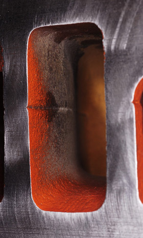
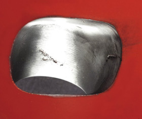
The stock exhaust port, shot from the exit.
Image: CHpg Staff.
|
 |
|
The exhaust port in a DeGroff head. Image: CHpg
Staff.
|
With
porting work done, it was time for the valves,
themselves. There are three options for larger valves in
3800 heads. If you're budget-constrained, valves out of
a '97-'04 Corvette's LS1 V8 work, provided you: 1)
reduce the intake to 1.90", 2) with the .175" longer
valves, use .175" shorter pushrods, 3) shim the springs
and 4) know that longer valves and shorter pushrods make
valvetrain geometry less than ideal, but acceptable, as
long as use above 6000 rpm is avoided.
If
you're building an all-out, racing 3800 and cost is no
object, try INTENSE-Racing "Severe Duty" valves.
Developed for 450+ hp. supercharged or turbocharged
3800s and made by Manley Performance Products, they're
stock length, but have 5/16" stems, so you must install
5/16" guides.
Wanting
to avoid geometry issues and figuring Severe Duty valves
were unnecessary to make 260-hp on the motor and 320-hp
with nitrous, we split the difference and
special-ordered Manley, "Gen II Race Master" valves (PN
11204 and 11205) which have stock diameter (8mm) stems.
We specified 1.90," intake, and 1.55," exhaust,
diameters, stock-length and lock grooves in the stock
locations. The Manley intakes are made of NK-842
stainless steel and the exhausts are made of XH-426
stainless which has good reliability and durability at
up to 1200°F. Both have stems hard-chromed to .002"
depth and swirl-polished heads.
 |
|
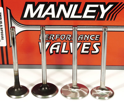
Stock valves (left pair) and the Manley Race
Master valves. The Manleys have stock stem diameters,
are stock length and use stock valve locks. Image: CHpg
Staff.
|
 |
|
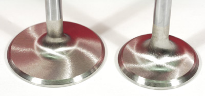
Look at those pretty, swirl-polished heads on
our Manley valves! Image: CHpg Staff. |
|
 |
|
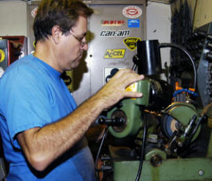
The valves were faced with a Sunnen valve
grinding machine. Image: CHpg Staff |
|
Manley Race Masters are an excellent choice for
our application, unblown, nitrous oxide,
under-8000 rpm in an aggressive,
high-performance street or racing duty cycle.
While costing more than LS1 pieces, Gen II Race
Masters preserve proper valve train geometry and cost a
third less than Severe Duty units plus--you don't need
new guides. Mark DeGroff chucked the Manley intake and
exhaust valves in his Sunnen valve grinding machine and
put a two-angle, 30°/45° face on each. |
The
next step was to move the heads back to the Serdi
Machine and do the final cut of the valve seats. The
precision Serdi is a real time saver
in that it cuts all the valve seat angles at
once with better accuracy than
old-style, valve seat grinders. In addition, when
necessary, it can machine curved surfaces rather than
multiple angles. For the intake seats, Mark fitted the Serdi with a specially-made cutter, selected by DeGroff
Cylinder Head Service for optimum results in
high-performance applications, which cuts a five-angle
seat (35°, 45°, 55°, 65°, 75°) with the 45° seat angle
1mm wide. On the exhausts, DeGroff used his own #1
High-Performance cutter to machine a
two-angle-plus-radiused seat which starts with a 30° top
cut, goes to a 45deg 1.5mm wide seat then a 10mm
descending radius where the seat transitions to the
bowl. The final step was the time-honored hand lapping
of the valves and seats.
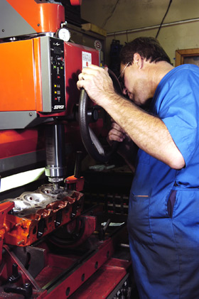 |
|
Mark DeGroff at the controls of the Serdi 60,
finishing-up the valve seats. Image: CHpg Staff. |
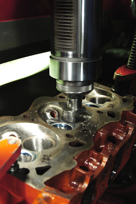 |
|
The Serdi uses a pilot in the valve guide to
index. Valve seats are machined rather than ground.
Image: CHpg Staff.
|
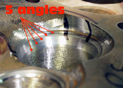 |
|
An enhancement to accuracy and time savings is
that the Serdi cuts all angles or radii of a muti-angle
valve seat at once. Image: CHpg Staff. |
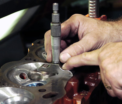 |
|
The valve seats are cut such that the valve is a
specific distance below the head deck and that dimension
is checked with a depth micrometer.
Image: CHpg Staff. |
 |
|
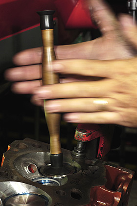
The final step in a DeGroff street port/polish
job is hand-lapping of the valve faces and seats. Image:
CHpg Staff.
|
 |
|
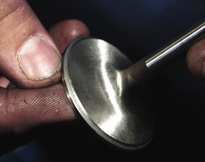
One of our Manleys, lapped and ready for final
assembly. Image: CHpg Staff. |
 |
|
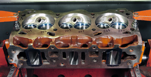
A DeGroff 3800 Series II head, ready for final
flow test. Image: CHpg Staff.
|
Next,
it was back to DeGroff's Quadrant Scientific flow bench
to test our work. The results in the tables below were
achieved with a test pressure of 28 inches of water.
Production
|
Lift
inches |
Intake Flow
CFM |
Exhaust Flow
CFM |
Ratio |
|
.100 |
56.8 |
45.8 |
.80 |
|
.200 |
112.8 |
100.2 |
.92 |
|
.300 |
159.0 |
132.0 |
.81 |
|
.400 |
180.6 |
144.7 |
.78 |
|
.500 |
188.0 |
145.5 |
.76 |
|
.600 |
192.6 |
151.3 |
.76 |
DeGroff modified
|
Lift
Inches |
Intake Flow
CFM |
Change |
Exhaust Flow
CFM |
Change |
Ratio |
|
.100 |
71.9 |
22% |
59.22 |
28.8% |
.82 |
|
.200 |
134.7 |
21% |
124.8 |
22.2% |
.93 |
|
.300 |
189.7 |
17% |
152.2 |
15.4% |
.88 |
|
.400 |
202.8 |
10% |
167.0 |
12.2% |
.82 |
|
.500 |
208.5 |
6% |
172.7 |
16.1% |
.85 |
|
.600 |
212.2 |
8% |
173.1 |
15.4% |
.82 |
As you can see, we achieved the goals set at the onset
of our head modification program.
|
 |
|
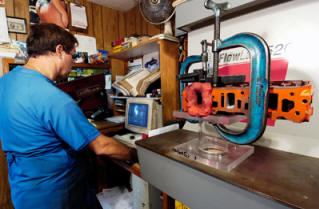
The flow bench never lies. The big C-clamp and
the modeling clay might not be high-tech, but they work
well. The FlowLab equipment is no longer made, perhaps
because it was too technologically-advanced and
expensive but, through its computer-controlled
automation, it quickly and accurately flow tests a port.
Image: CHpg Staff. |
|
After an earlier version of this article was published
in the Spring of 2006 in
Camaro Performers
magazine, some members of V6 forum sites were aghast
that we didn't use Abbott Racing Heads for our port
work. Typical of childish behavior sometimes exhibited
on forums, there were even expletive-laced tantrums
posted because we didn't use the head porting vendor the
"clique of experts" felt was best.
Drag racer Lance Abbott has done a lot of racing 3800
cylinder head development using his V6-powered '98
Pontiac Firebird drag racer. Lance told us in a recent
telephone conversation that he's run a 12.48 using his
ported intake, his Stage 3 head, a special Comp Cam,
long-tube headers and a pair of ET Street tires on the
rear. That's one potent 3800! |
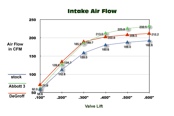
Abbott Racing Heads offers three modified cylinder heads
for '95-'02 V6es. Flow numbers on the Abbott web site
show the intake port in their "Stage 3" head clearly
outperforms our DeGroff heads once you go past about
.350" valve lift but we'd expect nothing less from a
head Abbott characterized as an all-out drag racing part
and listed on his web site as containing,
"...every ounce of our 30 years of head porting
experience. We believe these heads will out-perform any
other heads on the market."
People who actually know why certain cylinder head
modifications work understand that intake ports in a set
of heads intended for street high-performance use rather
than hardcore drag racing, may not flow as well at high
valve lifts.
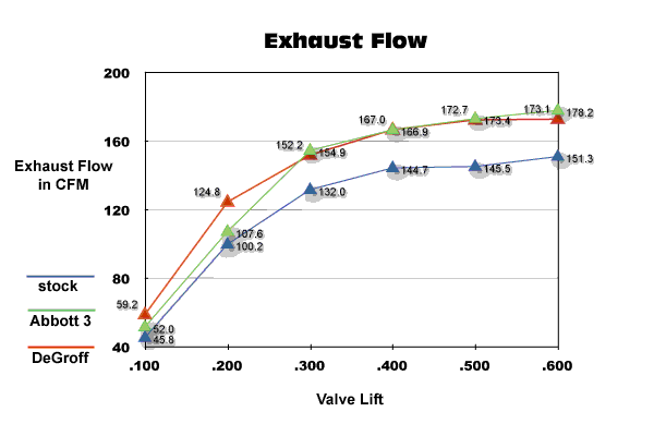
The flow data, also, shows that,
below .300" lift, our DeGroff heads are, actually ,
a little better than the Abbotts. The DeGroff
exhaust, also, flows better below .300" lift than the
Abbott 3 and, interestingly enough, above .300", the
DeGroff exhausts have similar flow characteristics to
the Abbottt.
 |
| |
 |
|
Intake and exhaust flow charts for stock,
Abbott Stage 3 and DeGroff heads. Graphics: CHpg
Staff.
|
If you want the ultimate 3800 head for drag racing, you
need a vendor experienced with racing head development
for that engine and Abbott Racing Heads is a good
choice. On the other hand, if you're building a 3800 for
street high-performance where good drivability, snappy
throttle response and a wide torque curve is important,
then, on the basis of its superior low-lift flow
numbers; maybe the DeGroff is a better alternative.
|
 |
|
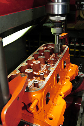
The final machining step
with the heads was to lower the valve
guide stem seals by machining the top of
guide. If you're going to use a cam with
over .450" lift, you must perform this
step to prevent contact between the stem
seal and the valve retainer.
Image: CHpg Staff. |
|
Lance Abbott spent countless hours developing his intake
ports and has validated that work with extensive flow
testing along with a lot of drag strip testing. There is
little doubt as to the fruits of this work as Lance's
car as gone mid-12s.
On the other hand, Mark DeGroff had never ported a set
of 3800 heads before we walked in his shop and he only
did one set for this project. In his first and only
attempt, we about equalled or exceeded the air flow
numbers of an all-out racing head except for intake flow
above .350" lift and, we were ok with that because these
were street heads. We wanted modest rather than
drag-race-style intake ports. It'll be interesting what
the kids on the forums have to say, now.
|
 |
 |
|
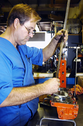
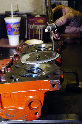
Near the end of the port/polish process, Mark
checks the combustion chamber displacement. Image: CHpg
Staff.
|
You seal-off the chamber with a section of
plastic, then fill the chamber with solvent
from a
burette and note the amount of solvent used. That figure
is the chamber displacement. Image: CHpg Staff. |
With
our airflow testing complete, Mark chucked each head
back in the Serdi and machined the tops of the valve
guides. This must be done to gain adequate clearance
between they and the valve spring retainers at maximum
valve lift when a high-lift cam is used. That was
followed by displacement-balancing (or "CC'ing") the
combustion chambers. At this point the head work was
complete.
The
Camaro Homepage's "Top Eight Things to Remember about
Porting 3800 Heads"
1)
Ports in heads which make good power are designed with
size and shape in mind, not just maximum flow at maximum
valve lift.
2) Big
ports make impressive flow numbers, but maybe not a
quick-revving engine. To make power in a hurry, you want
air velocity in the intake ports. Smaller ports with big
flow numbers have velocity.
3) The
short side radius on the intake port is the most
important area in the cylinder head.
4) Most
of the air/fuel mixture flows across as little as 120
degrees of the intake valve's circumference.
5) The
blend area, above the exhaust valve seat is critical to
good flow.
6) You
need a sharp break at the exhaust port exit, not the
common 35- or 38-degree angle.
7) The
color of combustion residue in the chamber tells much
about where the mixture is burning. Ideally, you want
consistent coloration throughout the chamber.
8)
Low-lift flow (.100-.300" lift) is critical to an engine
that revs quick everywhere in its torque curve. You
can't see this on the dyno, but if the heads don't flow
well at low valve lifts; drivers will say that the
engine has poor response.
After a
thorough solvent wash of all parts, DeGroff installed
the valve stem seals out of a Fel-Pro gasket set (PN HS
9917 PT-2), slipped the Manley valves back in place,
added retainers and locks (then measured spring heights
at 1.790" to 1.800", right at the desired, 1.800".
We're
at one of the places in this series where the Tom Henry
RS project on the Camaro Homepage differs dramatically
with the magazine series which published in
Camaro
Performers
during 2005 and 2006, on which this is based. For the
magazine series we used Comp valve springs, retainers
and locks along with the SLP 1.8 rockers. Unfortunately,
that combination didn't work well above 5800 rpm. Beyond
that, there was a significant torque loss caused by
valve float. To complete the project for the magazine,
deadlines forced us to go back to the stock, 1.6:1
rockers to end the valve float. For the Internet version
of this project, because we had more time to solve the
problem, we decided a more sensible solution was to
change some other valvetrain parts to eliminate the
valve float.
Katech,
Inc. (see sidebar) is one of the top Chevrolet race
engine development firms in the World. Its engines have
powered Corvette C5-Rs and C6.Rs to five wins at the 24
Hours of LeMans and six American LeMans Series
Championships in the last eight years.
We
figured there were few better experts on racing and
high-performance valvetrains in GM V6 and V8 engines
than Katech. Since, like the Gen 3/4 V8 family, the 3800
is an OHV engine and since it uses the same lifter,
spring, retainer and lock designs as those V8s; we
figured Katech might have a few suggestions to help us
fix our valve float woes.
 |
|
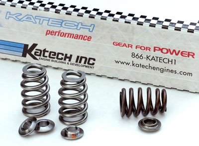
At right is a weak-suck, stock spring. At left
are the Katech springs which were originally designed
for Gen 3 V8 applications and are about the stiffest,
single, beehive spring available for a 3800. Image: CHpg
Staff. |
|
We
contacted Caleb Newman, Katech's Vice President and
Director of Aftermarket Operations. After a couple of
email exchanges and a telephone conversation with
Newman, we decided a little less valvetrain mass and a
slight increase in valve spring pressure might solve our
problem. The first step was to install Katech
Performance "High-Lift Beehive Valve Springs" (PN
PSI-LS1511) which spec at 125-lbs on the seat and
332-lbs open at .550" lift and 352-lbs at .600". This
spring is a bit more aggressive than the Comp 26918 (130
on the seat, 302 at .550" and 318 at .600") we used
initially. We hope the Katech springs along with
Katech's lighter retainers and a new, lower-mass, 1.8:1
rocker we'll tell you about in Pt. 3 will provide the
valvetrain stability we need.
|
|
 |
|
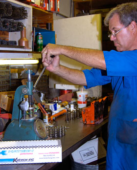
Each Katech spring was tested and met its
design specification. Always test
new springs. Image: CHpg
Staff. |
|
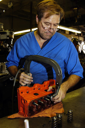
Mark
DeGroff tested each Katech spring and all met the
manufacturer's specs. He installed the springs, added a
set of Katech Performance 7° Titanum Retainers (PN
KAT-4678) put the locks in place and our set of DeGroff
heads was complete.
|
 |
|
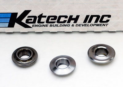
Why did we switch to Katech valve train
parts? Less mass is one reason. L-to-R
are, 10.1-gram, stock steel retainer, Katech's 5.2-gram titanium retainer and
Comp's 7.2-gram titanium retainer which we used
previously. |
|
 |
|
DeGroff, using an air-powered spring compressor
to assemble one of our heads. Image: CHpg Staff. |
Camshaft Selection and Installation
Flow testing validated our heads to .600 in. valve lift,
so we targeted .550" lift for our engine. Another issue
we considered is valve noise–the clacking you may hear
when the valves hit the seats in an engine fitted with
an aftermarket camshaft having aggressive closing ramps.
The faster the valve is going when it hits the seat, the
louder that noise will be. Some misidentify valve noise
as lifter noise because the two sound similar, however,
once you use a listening device to pinpoint the source,
it may be obvious that its valve seat noise and not
lifters you're hearing. Sometimes an engine controls'
knock sensing will be fooled by valve noise and the ECM
will enable knock retard (KR) even though no detonation
is present. We call this "false" knock retard.
Anytime you choose an aftermarket cam with
high-intensity lobes for an engine with knock sensors,
you walk a fine-line between having the most aggressive
lobe profile as possible and lobe profiles which are so
noisy when the valves close, that they cause false KR.
Another sticky issue with aftermarket cams and OBD II
engine controls is misfire detection. Many aftermarket,
performance cams have more overlap and lobe centerlines
which are closer together than a stocker. Both
situations may cause the engine to run rough at idle.
Problem is, if the idle is too lopey, OBD II may set a
diagnostic trouble code (DTC) P0300, which is random
misfire.
It is possible to disable certain features of the
on-board diagnostics by reprogramming to preclude the
system from setting misfire codes but that requires
either an experienced calibration engineer or your own
skills with engine controls cal software such as "HP
Tuners".
But, it's too easy to disable parts of OBD II. We like
the challenge in modifying our V6 to the 260hp level but
doing it in such a way that all engine controls
diagnostics continue to function properly, the engine
idles nicely and the engine's exhaust emissions such
that the car can pass the most stringent state exhaust
emissions tests, such as California's infamous BAR97
type "Smog Check". Only those with enough tuning
knowledge to be dangerous or those who are just lazy
avoid this challenge by disabling on-board diagnostics
on street-legal engines.
|
 |
|
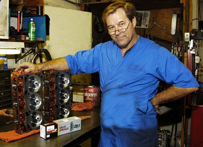
Mark DeGroff and a set of his 3800 heads. These
heads match some of the best, drag race heads in the
3800 racing community except for flow above .350" lift. DeGroff heads are a perfect choice for a street
high-performance 3800 of 225-275 hp. Image: CHpg Staff. |
Comp Cams has an assortment of 3800 series II cams in
its catalog, however, Comp Engineer, Billy Godbold
suggested a custom-ground cam for this project. Comp
does that regularly and doesn't charge extra for it, so
we took his advice. The "Tom Henry RS cam" is a
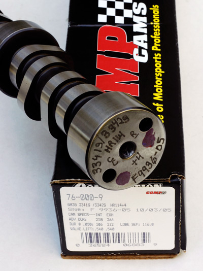
hydraulic roller (PN 76-0000-9) with a, #3341 intake
lobe and a #3342 exhaust. Duration at .050 in. lift is
206°, intake and 212°, exhaust. It's ground four degrees
advanced with a 116° lobe separation angle. With 1.6:1
rockers, valve lift is .480-in. With our 1.8:1 rocker
arms, valve lift will be .540", quite a bit more than
the stock, .413".
|
 |
|
The backside of the Comp Cams Tom Henry RS
camshaft shows Its custom grinding specs etched on the
of the rear journal. Image: CHpg Staff. |
|
 |
|
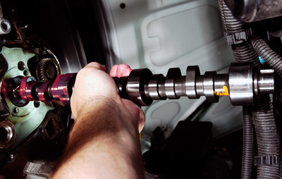
It's easiest to install the cam from below. Prelube the rear third, tip the rear of the cam up just
slightly and into the engine. As you do this, the front
of the cam will be just inside the passenger side
cooling fan. As the rear journal slides in, level the
cam then push the rear third into the engine. Lube the
remaining lobes and journals, then carefully push the
cam the rest of the way in. Image: CHpg Staff.
|
We pre-lubed the cam
with Red Line Engine Assembly Lube which has three times
the film strength of typical assembly lubes and will not
clog oil filters. We installed the cam then added a
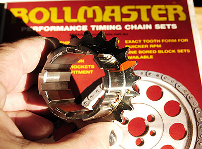
Rollmaster single- row timing chain set (PN CS6141). The
Rollmaster is one of the many 3.8 V6 performance parts
manufactured Australia where hot rodding those engines
is big. Rollmaster timing sets are distributed in the
States by the Engine Pro brand. We initially installed
our cam "straight-up", the Rollmaster's crank sprocket
has multiple keyways, allowing as much as 8° advance or
retard. Caution: with cam timing other than straight-up
or valve lift more than .550 in., check piston- to-valve
clearance. It's best to replace the chain damper anytime
the chain is changed, so we added that (PN 24503893)
which we ordered from GM Parts vendor, Tom Henry Racing.
|
 |
|
The crank sprocket for an Rollmaster
timing chain assembly. We've highlighted the TDC mark
with orange paint. The multiple keyways are how the
Rollmaster can be adjusted to alter cam phasing. Image:
CHpg Staff.
|
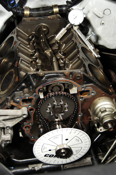
Camshaft degreeing validates cam timing and crankshaft
keyway indexing and is required during a cam change.
Comp Cams' has great camshaft checking equipment. We
used: TDC Deck Plate Stop (PN 4933), 7.5" Degree Wheel
(PN 4787), Crankshaft Socket (PN 4798), GM Cam Degree
Tool (PN 4925), and 1" Dial Indicator (PN 4909).
We used
the "intake centerline" (ICL) method to degree #1 and #3
intake lobes. We turned #1 intake to maximum lift,
zeroed the indicator then rolled the motor over until
got to the base circle and determined the ICL was 118°.
We checked #3 ICL and it, also, was at 118°.
We checked #3 ICL and it, also, was
at 118°. Once we advanced the cam 2°, using the
Rollmaster adjustable Timing Chain, ICL was the 116°
required by Comp Cams.
A detailed explanation of the intake centerline
procedure is in Comp Cams' instruction booklet.
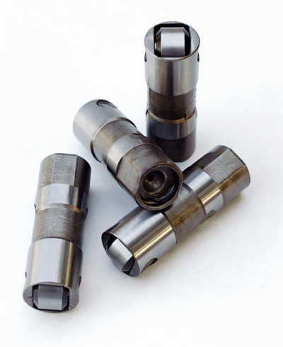
Lastly, we unpacked a set of Comp hydraulic roller
lifters (PN 875-12), to fill the lifters interiors, we
soaked them for several hours in Red Line 10W30
synthetic oil, then dropped them into the lifter bores.
Finally, we replaced the front cover using a Fel-Pro
Timing Cover gasket set (PN TCS45971) and tightened the
oil pan bolts.
|
 |
|
The Rollmaster chain assembly, damper and Comp
Cams degree tools are in place and we're ready to degree
the cam. Image: CHpg Staff.
|
.
|
 |
|
Comp Cams supplied the
hydraulic roller lifters. We selected Comp's
Pro Magnums because they'll handle fast
acceleration rates and a 6400 RPM rev limit
without pump-up. Image: CHpg Staff. |
The Tom
Henry RS project has a lot of sponsors, but a few
deserve special mention: INTENSE Racing's Scott Cook,
Comp Cams' Billy Godbold, cylinder head wizard Mark
DeGroff, Hypertech's Jim McFarland and Katech's Caleb
Newman went out of their way to help and we appreciate
their efforts.
In Part
Three of the Tom Henry RS project, we'll finish the
engine build-up and we'll do some mods to other parts of
the car. We'll see you back here in a few months.
Project Sponsors:
|
Comp Cams
3406 Democrat Rd.
Memphis, TN 38118
800 365 9145
www.compcams.com |
Mark DeGroff's Cylinder Head Service
18736 Parthenia #2
Northridge, CA 91324
818 701 5274 |
Eastwood Company
263 Shoemaker Rd.
Pottstown PA 19464
800 345 1178
www.eastwoodcompany.com |
Federal Mogul Corporation
(Fel-Pro)
26555 Northwestern Highway
Southfield, Michigan 48034
248-354-7700
www.federal-mogul.com/aftermarket |
Katech, Inc.
24324 Sorrentino Ct.
Clinton Township MI 48035
586.791.4120
www.katechengines.com |
Haynes Publications, Inc.
861 Lawrence Dr.
Newbury Park, CA 91320
800 442 9637
www.haynes.com/na.html |
|
Helm, Inc. (GM Service Manuals)
14310 Hamilton Ave.
Highland Park, MI 48203
800 782 4356
www.helminc.com |
Hypertech
3215 Appling Rd.
Bartlett TN 38133-3999
901 385 1888
www.hytpertech.com |
Per-Fit Corporation (Rollmaster)
728 S. Division
Grand Rapids, MI 49503
616 247-6572
www.romacusa.com |
Mac Tools
505 N. Cleveland Av.
Westerville OH 43082
800 622 8665
www.mactools.com |
Manley Performance Products
1960 Swarthmore Av.
Lakewood NJ 08701
800.526.1362
www.manleyperformance.com |
Red Line Synthetic Oil Corp.
6100 Egret Court
Benicia CA 94510
800 624 7958
www.redlineoil.com |
|
SPX
Kent-Moore
28635
Mound Road
Warren,
Michigan 48092-3499
800-468-6657
www.spxkentmoore.com |
|
Tom Henry Racing
5886 Route 8
Bakerstown PA 15007
877 866 7278
www.tomhenryracing.com |
|